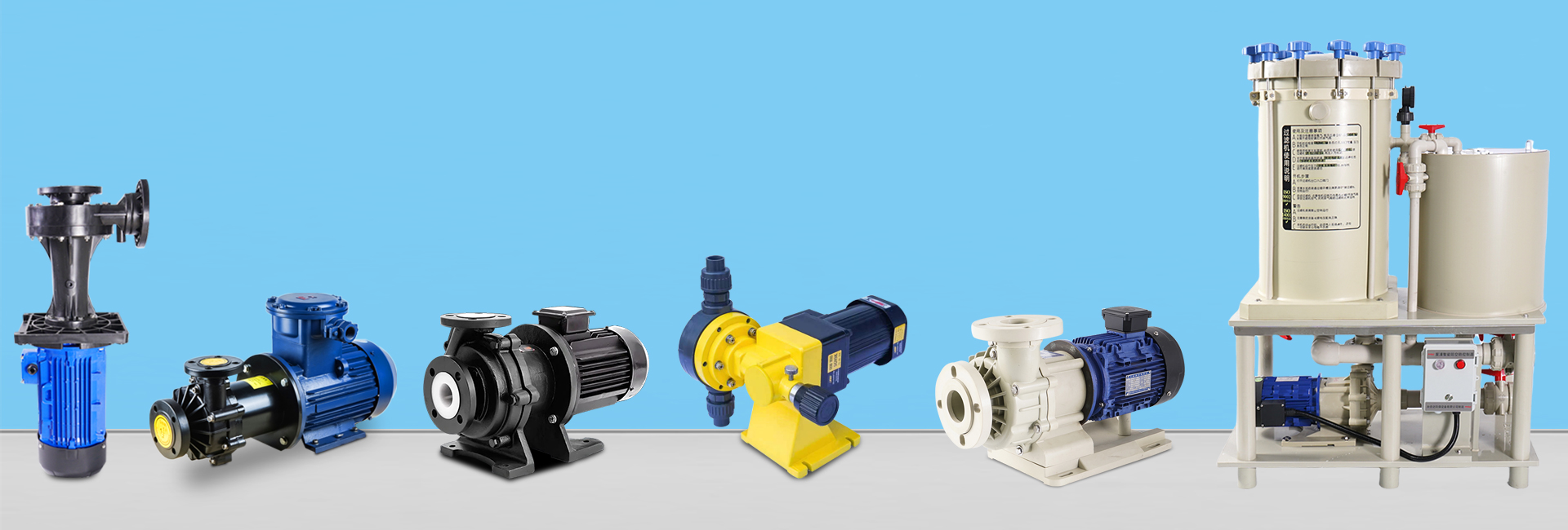

In industrial fluid handling, selecting the right pump type is crucial for ensuring efficiency, safety, and long-term reliability. Among the most common pump types are centrifugal pumps, self-priming pumps, and magnetic drive pumps.
Although they share similar hydraulic principles, their internal structures, sealing methods, and operational features differ significantly—each designed to solve specific engineering challenges such as priming, leakage, and corrosion resistance.
1. Centrifugal Pump — The Basic “Centrifugal Force Driven” Design
1.1 Core Structure
Centrifugal pumps operate based on the conversion of mechanical energy into kinetic and pressure energy. The key components include:
Impeller – The heart of the pump, consisting of multiple blades (open, semi-open, or closed type). It rotates at high speed (usually 1450 or 2900 r/min) to impart velocity to the liquid.
Pump Casing (Volute) – A spiral-shaped housing that converts the liquid’s velocity energy into pressure energy as it exits the impeller.
Shaft Seal – Prevents leakage between the rotating shaft and the stationary casing. Mechanical seals are most common, though packing seals are used in low-pressure systems.
Suction Chamber – Guides the incoming liquid smoothly into the impeller to minimize turbulence and hydraulic losses.
1.2 Working Principle
Before starting, the pump must be filled with liquid (a process known as priming). If air remains inside, centrifugal force cannot create sufficient vacuum for suction—resulting in “air binding” and possible mechanical seal damage due to dry running.
Once primed, the impeller rotates, throwing the liquid outward due to centrifugal force, creating a low-pressure area at the impeller center. Atmospheric pressure then pushes the liquid from the suction pipe into the pump, enabling continuous suction–discharge circulation.
1.3 Performance Characteristics
Flow Rate: Typically 1–1000 m³/h
Head Range: 10–200 m
Efficiency: 70%–90% under design conditions; efficiency drops when deviating from optimal flow.
Liquid Compatibility: Suitable for low-viscosity liquids (≤50 cSt) and small, soft particles (≤3 mm).
Installation Limitation: Suction lift ≤7 m; excessive suction height or high liquid temperature can cause cavitation (vapor bubbles damaging the impeller).
1.4 Typical Applications
Industrial: Cooling water circulation, boiler feedwater, pre-treatment in wastewater systems
Municipal: Water supply, drainage, and treatment plants
Agricultural: Large-scale irrigation and water transfer systems
1.5 Advantages & Disadvantages
Advantages:
Simple structure and low cost
Easy maintenance (mechanical seal replacement)
Stable flow and reliable operation
Disadvantages:
Requires manual priming before start
Risk of leakage from seal wear
Unsuitable for high-viscosity or abrasive fluids
2. Self-Priming Pump — The “No Manual Priming Needed” Evolution
2.1 Core Structure
A self-priming pump is an enhanced centrifugal pump with added components that enable automatic priming:
Liquid Reservoir: Stores liquid in the casing for the next startup.
Gas–Liquid Separation Chamber: Separates air from the liquid during startup.
Reflux Valve: Prevents the liquid from flowing back into the suction line when the pump stops.
2.2 Working Principle
During initial startup, the reservoir is manually filled once. When the impeller begins to rotate, the stored liquid mixes with the air in the suction pipe, forming a gas–liquid mixture.
Inside the separation chamber, air escapes through the vent while liquid returns to the impeller for recirculation.
As air is expelled, vacuum pressure builds in the suction pipe, allowing external liquid to be drawn into the pump automatically.
Once the pump is fully primed, it operates like a standard centrifugal pump.
Self-priming typically takes 30 seconds to 5 minutes, depending on suction height and pipeline length.
2.3 Performance Characteristics
Self-Priming Height: Typically 3–8 m; higher suction requires longer priming time and lower efficiency.
Efficiency: 5–15% lower than centrifugal pumps due to air–liquid separation losses.
Liquid Compatibility: Suitable for clean or slightly contaminated liquids (rainwater, light sewage). Not suitable for highly viscous (>100 cSt) or gas-rich fluids.
Operation: Once primed, restarts automatically without manual filling.
2.4 Typical Applications
Mobile Operations: Emergency drainage, truck-mounted pumps, marine water supply.
Rural & Remote Use: Drawing water from open tanks or shallow wells.
Intermittent Systems: Home water boosting, small-scale irrigation.
2.5 Advantages & Disadvantages
Advantages:
No manual priming required after initial startup
Convenient for mobile or intermittent use
Simple structure and easy maintenance
Disadvantages:
Longer self-priming time
Slightly lower efficiency
Requires periodic cleaning of the reservoir
Limited head (≤50 m)
3. Magnetic Drive Pump — The “Zero-Leakage” Upgrade
3.1 Core Structure
A magnetic drive pump eliminates the mechanical seal entirely, using magnetic coupling to transmit torque from the motor to the impeller:
Inner Magnetic Rotor: Connected directly to the impeller and sealed within the pump casing.
Outer Magnetic Rotor: Attached to the motor shaft, magnetically coupled with the inner rotor.
Isolation Sleeve: A non-magnetic barrier (made of stainless steel, titanium, or ceramic) separating the wet and dry sides.
Slide Bearings: Graphite or silicon carbide bearings lubricated by the pumped fluid.
3.2 Working Principle
The motor drives the outer magnet, which in turn drives the inner magnet through the isolation sleeve using magnetic field coupling.
This allows contact-free torque transmission, completely isolating the liquid from the motor—achieving true leak-free operation.
3.3 Performance Characteristics
Leakage: Zero leakage under normal conditions.
Efficiency: 5–20% lower than centrifugal pumps due to magnetic coupling losses.
Fluid Requirements: Non-granular, non-ferromagnetic, low-viscosity fluids (≤100 cSt).
Critical Limitation: Cannot run dry; lack of liquid cooling causes bearing failure and magnet demagnetization within seconds.
3.4 Typical Applications
Chemical Processing: Acids, alkalis, solvents, toxic or corrosive liquids
Pharmaceutical / Food: Sterile liquids and additives
Petroleum: Flammable fuels (gasoline, kerosene) for explosion-proof environments
Environmental Protection: Handling hazardous wastewater
3.5 Advantages & Disadvantages
Advantages:
Absolute leak-free design
Low maintenance (no seal wear)
Compact and space-saving
Disadvantages:
Higher cost (2–5× centrifugal pump)
Strict liquid purity requirements (requires fine filtration)
Complex maintenance (magnet or sleeve replacement)
Limited head (≤100 m) and flow rate (≤100 m³/h)
4. Comparison Table: Centrifugal vs Self-Priming vs Magnetic Pump
| Dimension | Centrifugal Pump | Self-Priming Pump | Magnetic Pump |
|---|---|---|---|
| Core Feature | Basic hydraulic design | Built-in priming chamber & air separation | Magnetic coupling, no shaft seal |
| Sealing Type | Mechanical seal (leak risk) | Mechanical seal (leak risk) | Isolation sleeve (zero leakage) |
| Startup Condition | Must be fully primed | First priming only | Must be filled with liquid (no dry run) |
| Efficiency | 70%–90% | 60%–85% | 50%–80% |
| Viscosity Limit | ≤50 cSt | ≤100 cSt | ≤100 cSt |
| Particle Tolerance | ≤3 mm | ≤1 mm | ≤0.1 mm (filtered) |
| Relative Cost | 1× (base) | 1.2–1.5× | 2–5× |
| Maintenance Difficulty | Low | Medium | High |
5. Pump Selection Guide
For toxic, flammable, or highly corrosive liquids: Choose a magnetic drive pump for maximum safety and environmental protection.
For general water or wastewater:
If priming is easy (fixed tank, low suction): choose a centrifugal pump for high efficiency and low cost.
If priming is inconvenient (mobile or open system): choose a self-priming pump for ease of use.
6. Conclusion
While all three pumps rely on the same basic hydraulic principle, their design purposes differ fundamentally:
Centrifugal pumps focus on simplicity and cost-effectiveness.
Self-priming pumps prioritize convenience and mobility.
Magnetic drive pumps deliver safety and zero-leakage operation.
Understanding their structural differences, performance parameters, and operational constraints allows engineers and users to make precise, cost-efficient selections for each fluid application.