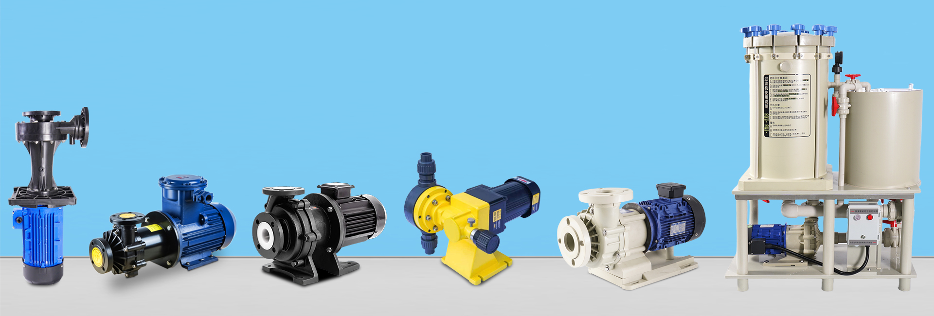
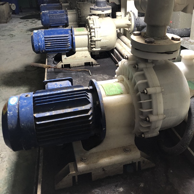
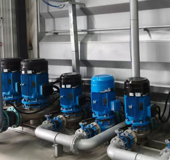
A magnetic pump is a seal-less centrifugal pump that relies on magnetic coupling for indirect power transmission. Its key advantage lies in solving the leakage issues of conventional centrifugal pumps caused by mechanical seal failures. Thanks to its zero-leakage design, the magnetic pump is widely used for transferring flammable, explosive, toxic, highly corrosive, or valuable media.
To thoroughly understand how a magnetic pump works, we can break it down into four layers: structural composition → power transmission path → core physical mechanism → operational characteristics.
1. Core Structure of a Magnetic Pump (Foundation of Its Principle)
The magnetic pump’s structure is built around static-dynamic isolation and magnetic transmission. It consists of five key components, each with specific material and functional requirements:
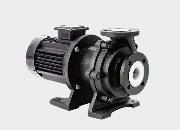
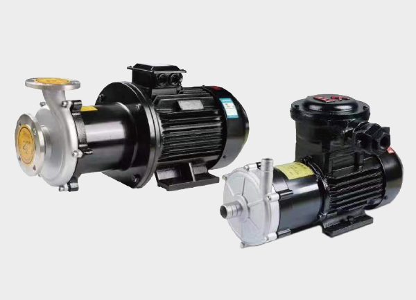
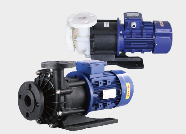
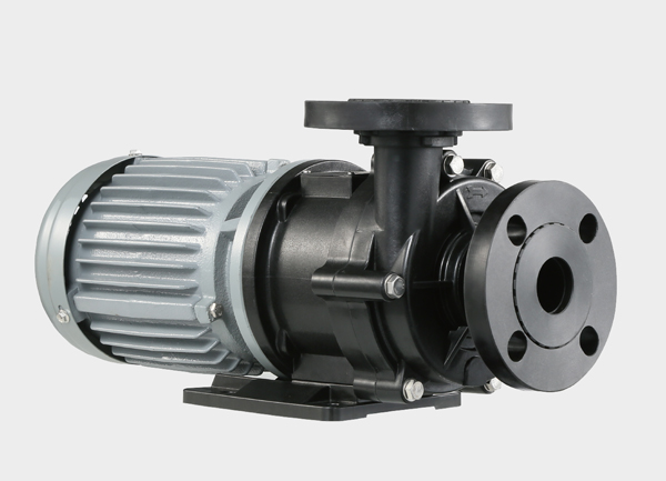
(1) Motor (Power Source)
Position & Material: Mounted outside the pump housing, usually a standard three-phase asynchronous motor. Depending on conditions (explosion-proof, anti-corrosion), the housing may be cast iron or stainless steel.
Function: Provides rotational power. The motor shaft is rigidly connected to the outer magnetic rotor, driving it to rotate synchronously with the motor.
(2) Outer Magnetic Rotor (Driving Magnet)
Position & Material: Fixed to the motor shaft end, located outside the containment shell. Made of rare-earth permanent magnets (NdFeB, SmCo) arranged alternately (N/S poles) within a non-magnetic hub.
Function: Produces a rotating magnetic field as it spins, serving as the primary energy source for magnetic coupling.
(3) Containment Shell (Isolation Barrier)
Position & Material: Between the inner and outer magnetic rotors; acts as the physical barrier separating the pumped fluid from the environment.
Material Requirements: Must be non-magnetic, high-strength, and low eddy-current loss. Common options: titanium alloy, Hastelloy (for high-pressure applications), or PTFE (for strong corrosion but low-pressure applications).
Functions:
Prevents fluid leakage (the heart of the zero-leakage guarantee).
Allows magnetic fields to penetrate with minimal attenuation.
(4) Inner Magnetic Rotor (Driven Magnet)
Position & Material: Located inside the pump chamber, rigidly connected to the impeller. Made of the same rare-earth permanent magnets as the outer rotor, with identical pole numbers and arrangement.
Function: Synchronously rotates under the pull-push force of the outer rotor’s magnetic field, transferring torque without direct contact to drive the impeller.
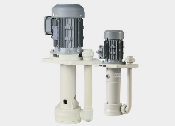
(5) Impeller & Pump Casing (Hydraulic Unit)
Position & Material: Impeller is connected to the inner magnetic rotor; casing forms the flow channel. Materials vary based on fluid corrosiveness (stainless steel, fluoroplastics, etc.).
Function: Converts rotational kinetic energy into fluid pressure energy by centrifugal action—drawing fluid in at the suction side and discharging it at the outlet, just like a conventional centrifugal pump.
2. Step-by-Step Power Transmission: How Does It Work Without Contact?
The essence of a magnetic pump is converting motor mechanical energy into fluid transport energy through magnetic coupling. The process can be divided into five steps:
Motor Starts → Motor shaft drives the outer magnetic rotor.
Magnetic Field Generation → Alternating N/S poles of the outer rotor create a rotating magnetic field, which penetrates the containment shell.
Magnetic Coupling → The inner rotor’s magnets experience alternating attraction-repulsion forces, causing it to rotate synchronously.
Impeller Rotation → Inner rotor drives the impeller, converting kinetic energy into fluid energy.
Zero Leakage → The containment shell keeps the pumped medium completely sealed inside, eliminating traditional shaft-seal leakage risks.
3. Core Physical Mechanisms of Magnetic Coupling
Two physical principles form the backbone of the magnetic pump:
(1) Synchronous Magnetic Coupling
Outer and inner rotors must have the same number of poles with precise alignment (e.g., 8-pole outer rotor requires 8-pole inner rotor).
This ensures synchronous torque transfer without slip, preventing torque loss or overheating.
(2) Eddy Current Loss in the Containment Shell
When the rotating magnetic field penetrates a conductive shell, eddy currents are induced, generating heat.
Risks:
Overheating → deformation or rupture of the containment shell.
Demagnetization of magnets if temperatures exceed the Curie point (e.g., ~310°C for NdFeB).
Solutions:
Use low-conductivity alloys (titanium has 1/5 the loss of stainless steel).
Use non-metallic shells (PTFE eliminates eddy currents).
Add cooling channels, letting part of the process fluid remove excess heat.
4. Operating Characteristics & Limitations
The working principle of a magnetic pump also defines its operational rules:
No Dry Running: Without fluid, eddy current heat cannot dissipate—magnets may demagnetize within minutes.
No Ferromagnetic Impurities: Iron filings or rust will block the magnetic gap and damage coupling.
Torque Limitation: If resistance exceeds maximum magnetic torque (e.g., high viscosity, clogged pipelines), the rotors will “decouple” (slip), protecting the motor and impeller.
Slightly Lower Efficiency: Due to magnetic and eddy current losses, efficiency is 3–8% lower than conventional centrifugal pumps.
5. Comparison: Magnetic Pump vs. Conventional Centrifugal Pump
| Aspect | Conventional Centrifugal Pump | Magnetic Pump | Key Difference |
|---|---|---|---|
| Sealing | Relies on mechanical seals (contact-based) | Sealed by containment shell (non-contact) | No shaft penetration in magnetic pumps |
| Leakage Risk | High – wear and tear of seals leads to leakage | Nearly zero – only possible if shell ruptures | Magnetic = inherently leak-free |
| Maintenance | High – seals replaced every 3–6 months | Low – no seals, fewer wear parts | Longer service intervals |
| Suitable Fluids | Clean, non-hazardous media | Toxic, flammable, corrosive, valuable fluids | Magnetic pump designed for high-risk applications |
Conclusion: Core Logic of the Magnetic Pump
In one sentence:
The motor drives the outer magnetic rotor → generates a rotating magnetic field → penetrates the containment shell → pulls the inner rotor into synchronous rotation → drives the impeller for fluid transfer, all while ensuring complete containment and zero leakage.
Essentially, a magnetic pump replaces mechanical shaft transmission with magnetic field transmission. By sacrificing a small portion of efficiency, it guarantees leak-free, safe, and reliable fluid handling—making it the preferred solution for industries dealing with hazardous or high-value media.