
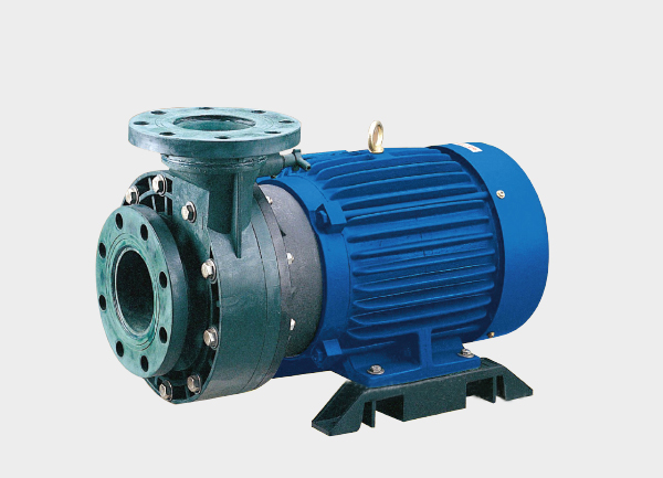
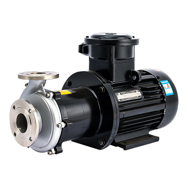
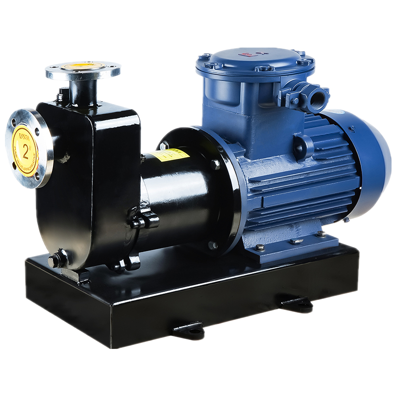
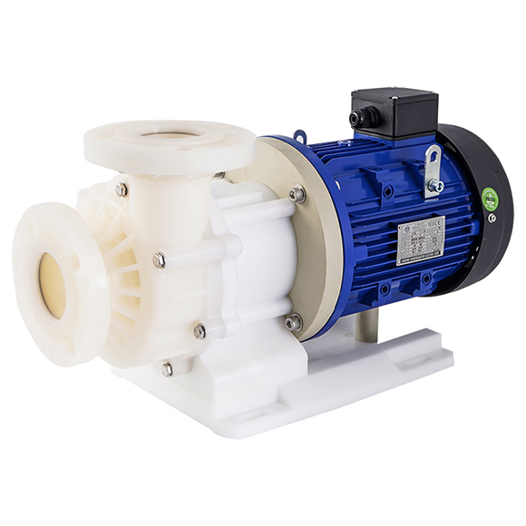
A fluoroplastic magnetic drive pump is a special type of centrifugal pump that combines magnetic coupling drive technology with fluoroplastic materials for wetted parts. It is specifically designed to handle highly corrosive, toxic, flammable, explosive, and valuable fluids with zero leakage, making it widely used in chemical processing, metallurgy, pharmaceuticals, and other industries where sealing reliability and corrosion resistance are critical.
This article provides an in-depth analysis across eight key dimensions: structure, working principle, performance, material selection, applications, pump selection guidelines, installation & maintenance, and common troubleshooting.
1. Core Structure and Components
The design of a fluoroplastic magnetic drive pump revolves around two goals: leak-free operation and superior corrosion resistance. Each component’s material and engineering directly determine the pump’s performance.
(a) Wetted Parts
These parts contact the medium directly and must resist corrosion and abrasion. Common fluoroplastic materials include:
PTFE (Polytetrafluoroethylene): Excellent corrosion resistance (up to 200°C), withstands nearly all chemicals (except molten alkali metals), but has low rigidity and tends to deform.
PVDF (Polyvinylidene fluoride): Moderate corrosion resistance (up to 150°C), stronger mechanical strength and impact resistance, suitable for fluids with light particulates.
FEP (Fluorinated ethylene propylene): Corrosion resistance close to PTFE, good moldability, widely used for impellers and complex shapes.
Most wetted parts are one-piece injection molded to eliminate leakage seams, with polished flow channels to reduce hydraulic losses and improve efficiency.
(b) Impeller
The impeller converts motor energy into kinetic energy for the liquid.
Typically closed impeller designs for efficiency.
For abrasive or particle-laden fluids, impellers may include inducers or cutting edges.
CFD optimization minimizes cavitation risk.
Small impeller-to-casing clearances (0.1–0.3 mm) reduce leakage losses.
(c) Magnetic Coupling Assembly
The heart of leak-free transmission, consisting of:
Inner magnetic rotor (NdFeB ≤120°C or SmCo ≤250°C, encapsulated in fluoroplastic).
Outer magnetic rotor (magnet steel encased in stainless steel).
Magnetic yoke (low-carbon steel for magnetic flux efficiency).
Design ensures symmetric magnetic fields, smooth torque transfer, and reduced rotor eccentricity. Cooling fans are often added to prevent magnet demagnetization due to overheating.
(d) Isolation Sleeve
This component isolates the fluid from the motor side, preventing leakage. Materials:
Thin-wall fluoroplastics (PTFE/PVDF) for pressures ≤1.6 MPa.
Metal alloys (Hastelloy, titanium) with fluoroplastic lining for higher pressures ≤4.0 MPa.
Thickness control (0.8–2 mm) is critical: too thick reduces torque transfer, too thin risks rupture.
(e) Bearings
Bearings support the rotor and reduce friction.
SiC (Silicon Carbide): High hardness, corrosion resistance, handles up to 600°C.
Si₃N₄ (Silicon Nitride): More toughness, better for fluids with fine particles or higher viscosity.
Bearings are typically fluid-lubricated by the pumped medium, avoiding external lubricants.
2. Working Principle: How Zero-Leakage is Achieved
Unlike conventional pumps with mechanical seals, fluoroplastic magnetic drive pumps rely on magnetic coupling.
Power Transfer: The motor drives the outer rotor, generating a rotating magnetic field.
Magnetic Coupling: The field passes through the isolation sleeve, driving the inner rotor.
Impeller Action: The inner rotor, rigidly connected to the impeller, rotates to move the fluid.
Sealing Integrity: The isolation sleeve fully separates the drive and fluid sides, ensuring zero leakage.
This eliminates seal wear, aging, and leakage problems common in mechanical seal pumps, providing nearly 100% leak-proof performance.
3. Key Performance Parameters
Flow Rate (Q): 1–500 m³/h (depends on impeller size & speed).
Head (H): 5–150 m (proportional to impeller speed²).
Temperature (T): -20°C to 200°C (PTFE/FEP up to 200°C, PVDF up to 150°C).
Viscosity (μ): ≤500 cP; higher viscosity reduces efficiency.
Particle Size: ≤0.5–5 mm (requires open impellers for larger particles).
Efficiency (η): 50–85% (slightly lower than mechanical seal pumps due to magnetic losses).
Working Pressure (P): 0.6–4.0 MPa, depending on sleeve material.
Performance Advantages
100% Leak-Free: Complies with API 685 and GB/T 32157 standards.
Exceptional Corrosion Resistance: Resistant to acids, alkalis, and oxidizers.
Low Maintenance: No seals or packing, ceramic bearings with 8,000–12,000 hr lifespan.
Stable Operation: Low vibration (≤0.05 mm), low noise (≤75 dB).
Explosion-Safe: No friction sparks; motors can be ATEX/IECEx compliant.
4. Fluoroplastic Material Selection
PTFE: Best for strong acids (HNO₃, HF, hot NaOH), high chemical resistance.
PVDF: Best for moderate acids, alkalis, electroplating fluids.
FEP: Easier to mold, good for impellers and covers at medium-high temperature.
PFA: Highest temperature resistance (up to 260°C), excellent durability but costly.
5. Application Industries
Petrochemical: Acidic water, sulfur-containing fluids, LNG methanol transfer.
Acid/Alkali Production: Chlor-alkali (NaOH, Cl₂), sulfuric acid.
Nonferrous Metallurgy: Acidic copper/nickel/rare earth solutions.
Pharmaceutical & Food: Hydrochloric/citric acid, GMP-compliant clean transfer.
Electroplating & Semiconductor: Nickel/chrome plating, HF cleaning fluids.
Environmental & Wastewater: Acid/alkali waste, flue gas desulfurization.
6. Pump Selection Guidelines
Identify Fluid Properties: Name, concentration, temperature, viscosity, particle size, flammability.
Define System Parameters: Flow rate, head (incl. pipeline losses), installation orientation.
Match Material: PTFE for strong acids/high T, PVDF for moderate T acids/alkalis, PFA for extreme T.
Optimize Design: Open impellers for particles, inducer impellers for cavitation risk, alloy sleeves for high pressure.
Performance Margin: Operate within 70–110% of rated point; keep temperature 20°C below material limit.
7. Installation and Maintenance
Installation Tips
Foundation levelness ≤0.1 mm/m.
Inlet diameter ≥ pump inlet, install Y-filter (≤0.5 mm mesh).
Install check valve (to prevent backflow) and gate valve (flow control).
Remove trapped air before startup to prevent vapor lock.
Maintenance Guidelines
Monitor bearing temp ≤70°C (stop >80°C).
Monitor motor current ≤110% of rated.
No external lubrication required (fluid-lubricated bearings).
For long shutdowns, flush and dry pump before storage.
8. Common Troubleshooting
No Flow / Low Flow: Check inlet blockage, remove trapped air, inspect impeller/magnets.
High Vibration / Noise: Check bearings, impeller balance, motor alignment.
Motor Overload: Reduce discharge valve opening, lower fluid viscosity, inspect rotor-sleeve clearance.
Isolation Sleeve Leakage: Replace with thicker or alloy-lined sleeve, check welds, redesign piping to reduce impact erosion.
9. Conclusion
The fluoroplastic magnetic drive pump offers a unique combination of leak-free operation and outstanding corrosion resistance, making it the ideal choice for hazardous, corrosive, and valuable fluids.
By selecting the right material, following proper installation, and maintaining regular inspections, these pumps can reliably operate for 3–5 years or more, ensuring safety, efficiency, and long service life in critical industrial applications.