You’ve raised an excellent question — understanding the working principle of a chemical metering pump is the key to proper selection, operation, and maintenance. Essentially, the chemical metering pump achieves accurate dosing through controlled volume variation or extrusion, where the core mechanism lies in “controllable displacement” and “adjustable flow.” The main differences between types of metering pumps depend on how the pump changes its internal volume or displaces fluid.
I. Core Common Principle of Chemical Metering Pumps
Regardless of the type, all chemical metering pumps operate on the same basic cycle of “suction–discharge + metering control,” which ensures precise fluid delivery.
1. Suction phase:
A vacuum is formed in the pump chamber; the inlet check valve opens while the outlet valve closes, allowing fluid to enter the chamber (or tube).
2. Discharge phase:
The pump chamber volume decreases or pressure is applied; the outlet check valve opens, the inlet closes, and the preset amount of fluid is discharged.
3. Metering control:
Flow is precisely controlled by adjusting either the displacement per stroke (stroke length) or the cycle frequency per unit time (motor speed). This ensures dosing accuracy within ±0.1% to ±3%.
II. Working Principles of the Three Main Types
In industrial applications, chemical metering pumps are commonly divided into plunger type, diaphragm type, and peristaltic type. Their principles differ in how they move or deform the pumping element — determining their best use cases.
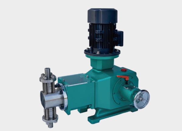
1. Plunger (Piston) Metering Pump — Volume Change by Piston Motion (Best for High Precision)
Main Components: Motor, eccentric cam (drive), plunger, pump cylinder, inlet/outlet check valves.
Working Process:
The motor drives the eccentric cam to move the plunger back and forth inside the cylinder.
When the plunger retracts, the chamber volume increases, creating negative pressure — the inlet valve opens and fluid enters.
When the plunger advances, the volume decreases, pressure rises, the outlet valve opens, and the fluid is expelled.
Flow Adjustment:
By changing the stroke length (the plunger’s maximum travel), the displacement per stroke is adjusted.
By changing the motor speed (frequency control), the number of strokes per unit time is controlled — thus adjusting total flow.
Key Features:
Direct contact between fluid and plunger provides extremely high accuracy (±0.1%–±1%). However, it relies heavily on sealing components to prevent leakage. Ideal for non-corrosive, high-pressure applications such as petrochemical dosing.
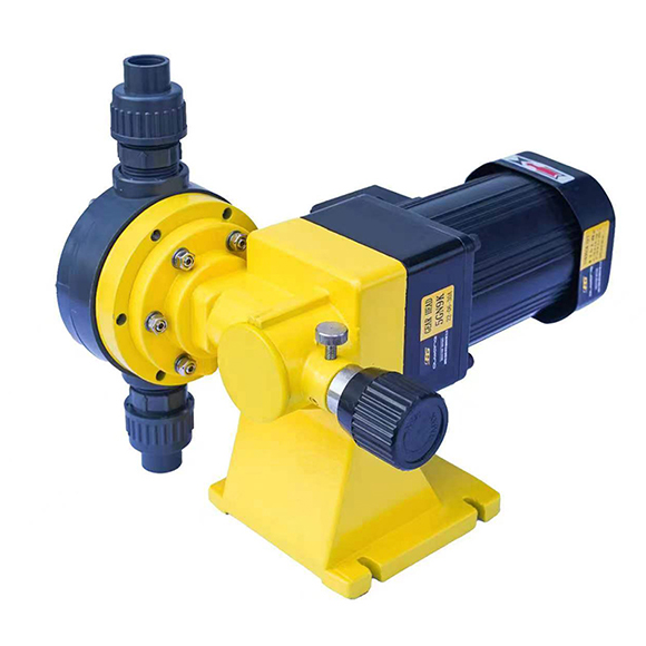
2. Diaphragm Metering Pump — Volume Change by Diaphragm Deformation (Best for Corrosion Resistance)
Main Components: Motor, drive mechanism, plunger (or hydraulic push rod), elastic diaphragm (PTFE or rubber), pump head, check valves.
Working Process (Mechanical Diaphragm Example):
The motor drives the plunger forward, pushing the diaphragm toward the pump chamber. The chamber volume decreases, outlet valve opens, and fluid is discharged.
As the plunger retracts, the diaphragm returns to its original position under elasticity, chamber volume increases, the inlet valve opens, and new fluid is drawn in.
Special Type — Hydraulic Diaphragm Pump:
Instead of directly moving the diaphragm, the plunger pushes hydraulic oil, which transmits pressure to deform the diaphragm. This allows much higher discharge pressures (up to 40 MPa), suitable for large flow and high-pressure applications.
Flow Adjustment:
Same as the plunger type — adjust stroke length or motor speed.
Key Features:
The diaphragm isolates the fluid completely from mechanical parts, ensuring zero leakage and excellent chemical resistance. Slightly lower accuracy (±0.5%–±2%) than plunger types. Widely used in water treatment and chemical dosing systems.
3. Peristaltic Metering Pump — Fluid Conveyed by Roller Compression (Best for Hygiene and Anti-Contamination)
Main Components: Motor, roller assembly (3–6 rollers), flexible tubing (silicone or rubber), and pump housing.
Working Process:
The motor rotates the roller assembly, pressing the flexible tube along its length.
As the roller moves forward, it pushes the trapped fluid segment toward the outlet — similar to squeezing toothpaste.
When the roller passes, the tube rebounds by elasticity, creating suction at the inlet and drawing in new fluid.
Flow Adjustment:
By changing the motor speed, the roller’s compression frequency — and thus the flow rate — is controlled.
By replacing the tube’s inner diameter, the displacement per rotation can be changed (requires shutdown).
Key Features:
Only the tube contacts the fluid, eliminating contamination risk. Ideal for pharmaceutical, food, or laboratory use, as well as viscous or particle-laden fluids (e.g., sludge, coatings). However, discharge pressure is lower (≤ 0.6 MPa).
III. Key Components Behind the Principle
To ensure accurate metering, two components are indispensable:
1. Check Valves (Inlet & Outlet):
They ensure unidirectional flow by preventing backflow. Clogging or wear can directly cause inaccurate dosing or complete flow loss.
2. Adjustment Mechanism:
Includes mechanical stroke regulators or electronic frequency converters. These control either stroke volume or delivery frequency, allowing 10%–100% adjustable flow range.