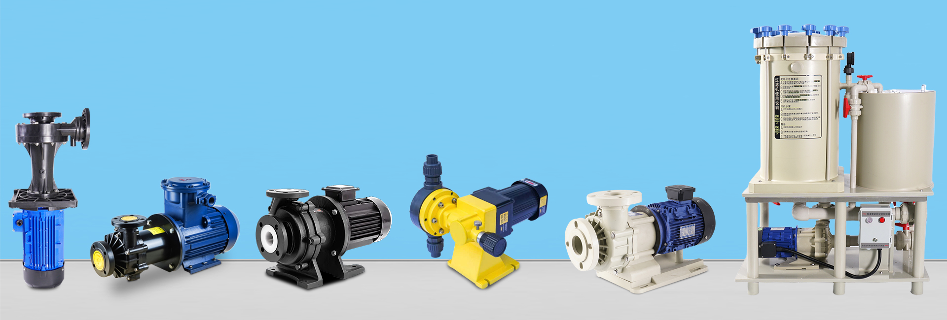
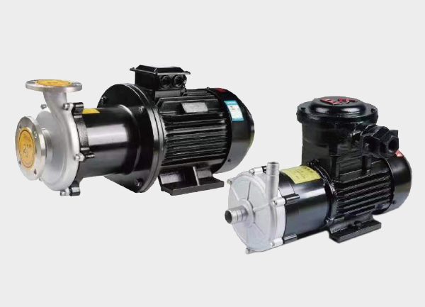
In chemical, water treatment, and energy industries, high-flow magnetic drive pumps (also known as magnetic centrifugal pumps) are gaining popularity for their leak-free performance and high-efficiency flow capacity. Understanding their structure, magnetic coupling mechanism, and selection criteria is crucial for safe and efficient operation. This article provides an in-depth analysis across four dimensions — core components and magnetic coupling, typical application scenarios, advantages and precautions, and key selection parameters — to help you choose and operate these pumps effectively.
1. Working Principle and Magnetic Coupling Technology
The “leak-free” and “high-flow” nature of magnetic drive pumps is not achieved by design alone — it relies on the precise function of each component and the type of magnetic coupling used.
1.1 Core Components and Their Functions
| Component | Main Function | Typical Materials (for high-flow / corrosive media) | Key Notes |
|---|---|---|---|
| Outer Magnetic Rotor | Transfers motor power via magnetic field to the inner rotor | Carbon steel + NdFeB magnets (for normal temp), Stainless steel + SmCo magnets (for high temp) | Must be coated for corrosion protection |
| Inner Magnetic Rotor | Rigidly connected to impeller, converts magnetic torque into rotation | Stainless steel + sealed magnet core | Keep free from ferromagnetic particles to maintain balance |
| Isolation Sleeve | Separates inner and outer rotors, forms sealed chamber (core of leak-free design) | Hastelloy (for corrosion), Duplex steel (for high pressure & flow) | Wall thickness critical: too thick reduces magnetic force; too thin risks rupture |
| Impeller | Generates centrifugal force, enabling suction and discharge | Stainless steel 316L, engineering plastics (for low-viscosity fluids) | Wide-open impeller design for reduced resistance and large flow |
| Pump Casing | Contains and guides liquid flow (inlet → impeller → outlet) | Cast iron (for clean water), stainless steel (for corrosive fluids) | Large inlet diameter (typically ≥DN80) for high-flow systems |
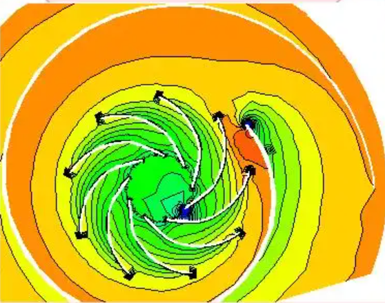
1.2 Types of Magnetic Coupling
Magnetic coupling transmits torque without physical contact, ensuring full isolation between the drive and the fluid chamber. Two main types are used:
Synchronous Magnetic Coupling
Principle: Inner and outer rotors rotate at identical speeds (no slip).
Advantages: High transmission efficiency (≥95%), ideal for large flow and low-viscosity fluids (e.g., water, acid/alkali solutions).
Limitations: Less tolerant of high viscosity or solid impurities — risk of overheating from magnetic lag.
Asynchronous Magnetic Coupling
Principle: Outer rotor speed is slightly higher (5–10% slip).
Advantages: Stronger impact resistance, suitable for fluids with slight impurities or moderate viscosity.
Limitations: Lower efficiency and higher energy consumption — rarely used for high-flow applications.
2. Typical Industrial Applications
A high-flow magnetic pump typically refers to a unit with a flow rate ≥50 m³/h, with heavy-duty models exceeding 1000 m³/h. Different industries impose distinct requirements for corrosion resistance, temperature tolerance, and material safety.
2.1 Chemical Industry (Primary Application Field)
Use Cases: Handling concentrated acids and alkalis (e.g., 30% sulfuric acid, 50% sodium hydroxide), organic solvents (methanol, ethylene glycol), or toxic media (acrylonitrile).
Key Requirements:
Corrosion-resistant materials — Hastelloy isolation sleeve, 316L stainless steel casing.
High flow stability — prevents pressure surges in process pipelines.
Magnetic rotor temperature monitoring — prevents magnet demagnetization caused by leakage or overheating.
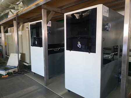
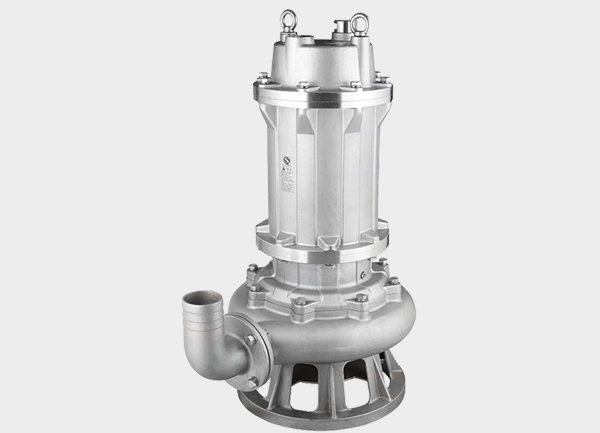
2.2 Water Treatment Industry (Largest Flow Demand)
Use Cases: Municipal wastewater supply, seawater desalination pretreatment, industrial cooling water systems.
Key Requirements:
Non-clog impeller design to prevent blockage by fibers or sand.
Moderate head (10–30 m typical), focus on large volume transfer.
Frequency control motor to adjust flow dynamically, saving energy.
2.3 Energy and Pharmaceutical Industries (Special Conditions)
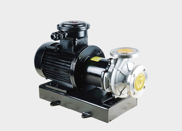
Energy Sector: Nuclear cooling systems (handling >150°C fluids, requiring SmCo magnets and heat-resistant sleeves), refinery solvent transfer (flammable media, explosion-proof motor).
Pharmaceutical Sector: Purified water or WFI (Water for Injection) transfer — sanitary-grade design with dead-zone-free chambers and sterilizable surfaces.
3. Advantages and Operational Precautions
3.1 Core Advantages
Zero Leakage Safety:
Eliminates mechanical seals and friction pairs (rotary and stationary rings), fully preventing axial seal leakage — ideal for toxic, flammable, or explosive liquids.Energy Efficiency in High Flow:
Wide impeller passage and low-resistance casing reduce power consumption by 30% compared with volumetric pumps (like diaphragm types), while maintenance intervals are typically 1–2 years.
3.2 Operational Considerations
Avoid Dry Running:
Without liquid cooling, the isolation sleeve can heat up above 200°C within one minute, causing melting or magnet demagnetization.
→ Solution: Install a liquid level sensor to trigger automatic shutdown when the chamber is empty.Limitations on Viscosity and Solids:
Viscosity >50 cSt increases resistance and may cause magnetic slip.
Particles >0.1 mm can abrade the impeller and sleeve.
→ Solution: Install a pre-filter (≤0.05 mm mesh) on the suction side for contaminated media.
Axial Thrust Balance:
High-flow impellers generate axial force toward the inlet, leading to bearing wear.
→ Solution: Choose impellers with balance holes or balance discs to counter thrust.
4. Key Selection Parameters
Selecting the right high-flow magnetic pump involves more than just flow rate. The following five parameters are critical for efficiency and reliability:
Design Flow Rate:
Choose a pump rated ≥ required flow +10% margin (e.g., 200 m³/h system → select ≥220 m³/h model).Net Positive Suction Head Required (NPSHr):
To prevent cavitation, ensure available NPSH (NPSHa) exceeds NPSHr by at least 0.5–1 m.Medium Temperature:
≤80°C → NdFeB magnets
80–200°C → SmCo magnets
200°C → Custom high-temp magnetic assembly
Fluid Viscosity:
≤50 cSt → standard design
50–100 cSt → higher motor power
100 cSt → use volumetric pump instead
Working Pressure:
Outlet pressure should match pipeline rating (usually ≤1.6 MPa for large-flow pumps). For high-pressure conditions, select reinforced casings and sleeves.
Conclusion
High-flow magnetic drive pumps combine contactless torque transmission, leak-free design, and energy-efficient operation, making them indispensable in chemical, environmental, and energy industries. By mastering their structure, coupling type, and selection principles, engineers can ensure safe, stable, and economical fluid transport — even under the most demanding industrial conditions.