1. What Is a Centrifugal Pump & How Does It Work?
1.1 Core Definition
1.2 Working Mechanism
- Pre-Startup Preparation: Fill the pump casing and suction pipe with liquid (except for self-priming models) to avoid dry running, which can damage internal components.
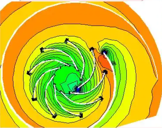
- Energy Input & Transfer: The motor drives the pump shaft, which in turn spins the impeller at high speed. The impeller’s blades push the liquid into circular motion, and centrifugal force flings the liquid from the impeller’s center to its outer edge—simultaneously increasing the liquid’s velocity and pressure.
- Energy Conversion & Delivery: The liquid expelled from the impeller enters the volute-shaped pump casing. The casing slows the liquid’s flow, converting its kinetic energy into pressure energy. Meanwhile, the impeller’s center creates a low-pressure zone (due to liquid being ), forming a pressure difference with the liquid source. This difference draws more liquid into the pump, creating a continuous “suction-discharge” cycle.
- Total Head Composition: A pump’s total head combines two components:
- Suction Head: Relies on atmospheric pressure to draw liquid into the pump (theoretical limit: ~10.336 meters of water column).
- Discharge Head: Generated by the impeller’s rotation to push liquid outward, determining the final outlet pressure.
2. Key Components of a Centrifugal Pump & Their Functions
| Component Category | Specific Component | Core Function |
|---|---|---|
| Core Working Components | Impeller | The “power core” of the pump. It transfers energy to the liquid via rotation; blade design directly impacts flow rate, head, and efficiency. |
| Pump Casing (Volute) | Provides structural support, collects liquid from the impeller, and facilitates the conversion of kinetic energy to pressure energy. It also guides liquid toward the discharge port. | |
| Pump Shaft | Acts as a “drive bridge” between the motor and impeller, transmitting mechanical energy to the impeller while ensuring smooth rotation. | |
| Auxiliary Support Components | Bearings | Support the pump shaft, reduce friction during rotation, and control radial/axial movement of the shaft. |
| Sealing Devices | Include wear rings (anti-leak rings), packing glands, or mechanical seals. They prevent high-pressure liquid leakage from the pump and stop air from entering (which would the vacuum). | |
| Suction/Discharge Ports | Control fluid inflow and outflow: The suction port connects to the liquid source, while the discharge port links to the delivery pipeline. Some models (e.g., end-suction pumps) have bottom-mounted discharge ports for easy disassembly and cleaning. | |
| Strainer (Filter) | Installed at the suction port to remove impurities from the fluid, preventing impeller clogging or wear. |
3. Main Types of Centrifugal Pumps & Their Characteristics
3.1 Classified by Number of Impellers
- Single-Stage Centrifugal Pumps: Feature one impeller. They have a simple structure and low cost, making them ideal for low-head applications such as agricultural irrigation, residential drainage, and small-scale water supply.
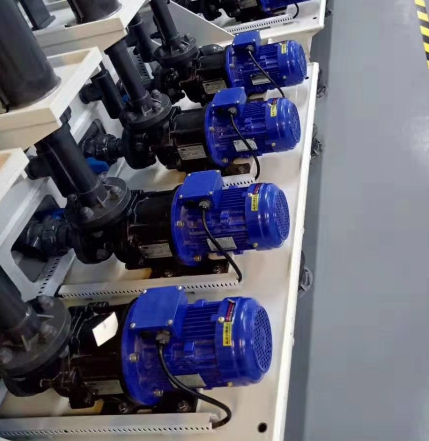
- Multi-Stage Centrifugal Pumps: Equipped with two or more impellers connected in series. The total head equals the sum of the heads of individual impellers, suiting high-head scenarios (e.g., high-rise building water supply, fire systems, high-pressure cleaning). Among them, vertical multi-stage pumps are compact and space-saving, perfect for continuous high-flow applications like irrigation in arid regions.
3.2 Classified by Fluid Flow Direction
- Axial-Flow Pumps: Liquid flows parallel to the pump shaft. They deliver high flow rates but low heads, suitable for large-volume transfer (e.g., municipal wastewater treatment, large-scale pumping station drainage).
- Radial-Flow Pumps (Centrifugal Pumps): Liquid flows perpendicular to the pump shaft. They generate high heads and pressure, making them suitable for high-pressure conditions (e.g., chemical high-pressure fluid transfer, boiler feedwater).
3.3 Classified by Installation & Suction Method
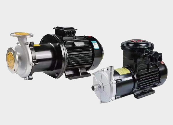
- End-Suction Pumps: Liquid is drawn from one side of the impeller. They offer high flow rates and efficiency, with bottom-mounted discharge ports. Some models include quick-disconnect couplings for easy disassembly and cleaning, making them ideal for food hygiene and processing industries (where cleanliness is critical).
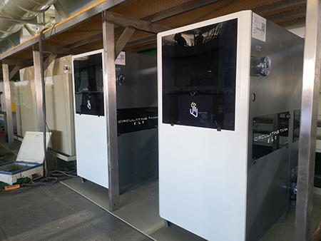
- Inline Pumps: Installed directly in the delivery pipeline, requiring no additional foundation. Their compact design suits HVAC systems (e.g., air conditioning water circulation, building heating).
- Self-Priming Pumps: Do not require pre-filling with liquid. They achieve self-priming via cavitation and centrifugal force. Self-priming sewage pumps, in particular, have higher displacement than air-suction models and lower installation costs. They are used for scenarios where liquid sources are inaccessible (e.g., chemical tanks, ships, recycling equipment).
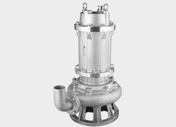
- Submersible Pumps: Operate fully submerged in liquid, eliminating the need for additional suction pipes. They are used for deep-well water extraction, underground garage drainage, and aquaculture aeration.
- Single-Suction/Double-Suction Pumps: Single-suction pumps draw liquid from one side of the impeller (simple structure). Double-suction pumps draw from both sides, delivering higher flow rates for large-scale applications (e.g., water treatment plants, power plant cooling systems).
3.4 Classified by Operating Pressure
- Low-Pressure Pumps: Head < 100 meters of water column (e.g., residential water supply, agricultural irrigation).
- Medium-Pressure Pumps: Head = 100–650 meters of water column (e.g., industrial process transfer).
- High-Pressure Pumps: Head > 650 meters of water column (e.g., high-pressure cleaning, oilfield water injection).
3.5 Specialized Pumps for Specific Scenarios
- Process Pumps: Operate on vacuum principles, withstanding high pressure. They are used for industrial process fluid transfer, laboratory media handling, and pollution/fire prevention.
4. Typical Applications of Centrifugal Pumps
4.1 Industrial Sector
- Chemical Industry: Transfer acidic/alkaline solutions, solvents, and other chemical media to support inter-process fluid movement.
- Oil & Gas Industry: Transport crude oil, refined oil, and natural gas associated liquids.
- Power Industry: Handle ash sluicing in thermal power plants, boiler feedwater, and cooling cycle systems in nuclear power plants.
- Metallurgy & Coal Industry: Transfer mineral slurries in mineral processing plants and coal slurries in coal washing plants.
4.2 Residential Sector
- Building Water Supply: Draw water from municipal pipelines or wells to provide pressurized water for high-rise buildings.
- HVAC Systems: Circulate hot/cold water in air conditioning and heating systems to maintain comfortable indoor temperatures.
- Water Treatment: Transfer clean water in waterworks and lift/recirculate wastewater in sewage treatment plants.
4.3 Agricultural Sector
- Irrigation Systems: Deliver water from rivers or wells to farmland for crop irrigation.
- Livestock Farming: Supply clean water to livestock and manage agricultural wastewater.
5. Pros & Cons of Centrifugal Pumps
5.1 Advantages
- Simple Structure & Compact Design: Small footprint and easy installation.
- Stable Operation & Low Noise: Suitable for noise-sensitive environments (e.g., residential buildings).
- High Efficiency & Low Maintenance Costs: Economical for long-term use, especially when handling low-viscosity fluids.
- Versatility: Adaptable to different fluids (corrosive, viscous) by changing materials (e.g., stainless steel, plastic).
- Safe Short-Term Operation: Can run briefly with closed discharge valves, no additional safety devices required.
5.2 Limitations
- Limited Suction Lift: Cannot be used in high-vacuum conditions; requires continuous liquid supply (no dry running).
- Limited Pressure Capacity: High-head applications require multi-stage impellers.
- Flow Rate Sensitivity: Flow rate is strongly affected by backpressure, less precise than positive displacement pumps.
- Impeller Wear Risk: Prone to wear when handling solid-laden fluids; efficiency drops significantly with high-viscosity fluids (>600 cSt).
- Shear Sensitivity: High-speed rotation may damage shear-sensitive fluids (e.g., dairy products, biological agents).
6. Maintenance, Troubleshooting & Safe Operation
6.1 Daily Maintenance Tips
- Regularly check for leaks in sealing devices; replace packing or mechanical seals if leaks occur.
- Inspect the impeller for wear or corrosion; replace it if blades are chipped or worn.
- Clean the suction strainer periodically to prevent clogging and reduced flow.
- Lubricate bearings as required (e.g., add lubricating oil) and keep bearing temperatures below 85°C (ideally ~60°C).
- Check the stability of motor and electrical connections to avoid overload from loose wiring.
- Drain liquid from the pump and apply anti-rust oil during long-term storage to prevent corrosion of the casing and impeller.
6.2 Common Faults & Solutions
| Common Fault | Possible Causes | Solutions |
|---|---|---|
| Cavitation (bubbles in the pump, accompanied by noise) | Low suction pressure, excessive suction lift, clogged suction pipe | Increase the liquid level at the suction source, reduce suction lift, clean the suction pipe and strainer |
| Insufficient Flow | Clogged strainer, worn/damaged impeller, low motor speed | Clean the strainer, replace the impeller, check the motor’s power supply voltage and speed |
| Pump Overheating | Inadequate bearing lubrication/deteriorated grease, motor overload, impeller-casing friction | Refill or replace lubricant, reduce motor load (e.g., partially close the discharge valve), adjust the gap between the impeller and casing |
| Seal Leakage | Worn seal faces, loose/aged packing, improper mechanical seal installation | Polish seal faces, tighten or replace packing, reinstall the mechanical seal |
6.3 Safe Operation Precautions
- Always disconnect the motor power before maintenance or inspection to prevent electric shock.
- Wear personal protective equipment (e.g., safety goggles, non-slip gloves, safety shoes) to avoid injury from fluid splashes or falling parts.
- Ensure the pump is properly grounded to prevent electrical accidents.
- Close the discharge valve before startup (to reduce startup load), then slowly open it once the motor reaches rated speed.
7. Conclusion & Future Trends
- Energy Efficiency: Optimized impeller designs and high-efficiency motors to reduce energy consumption.
- Automation: Integration of smart sensors for real-time monitoring of flow rate, pressure, and temperature, enabling predictive maintenance and fault alerts.
- Corrosion Resistance: Adoption of new alloys and composite materials to enhance durability in harsh environments (e.g., strong corrosive fluids).
8. Frequently Asked Questions (FAQs)
A1: A high-speed rotating impeller generates centrifugal force to fling liquid from its center to the outer edge, converting kinetic energy into pressure energy via the pump casing—enabling continuous fluid transfer.
A2: Core components include the impeller (energy transfer), pump casing (energy conversion), and pump shaft (power transmission). Auxiliary components include bearings (friction reduction), sealing devices (leak prevention), and suction/discharge ports (flow control).
A3: Self-priming pumps are ideal for scenarios where pre-filling liquid is inconvenient or the liquid source is inaccessible (e.g., chemical tanks, ships, outdoor temporary pumping). They eliminate the need for manual priming.
A4: Dry running removes the liquid lubrication between internal components (e.g., seals, bearings), causing rapid wear or overheating. It also prevents the formation of a low-pressure zone, rendering the pump unable to draw liquid.
A5: Select open-impeller designs (better for viscous fluids) and reduce the pump speed to minimize efficiency loss. Regularly inspect the impeller and seals for wear, as high viscosity increases friction.