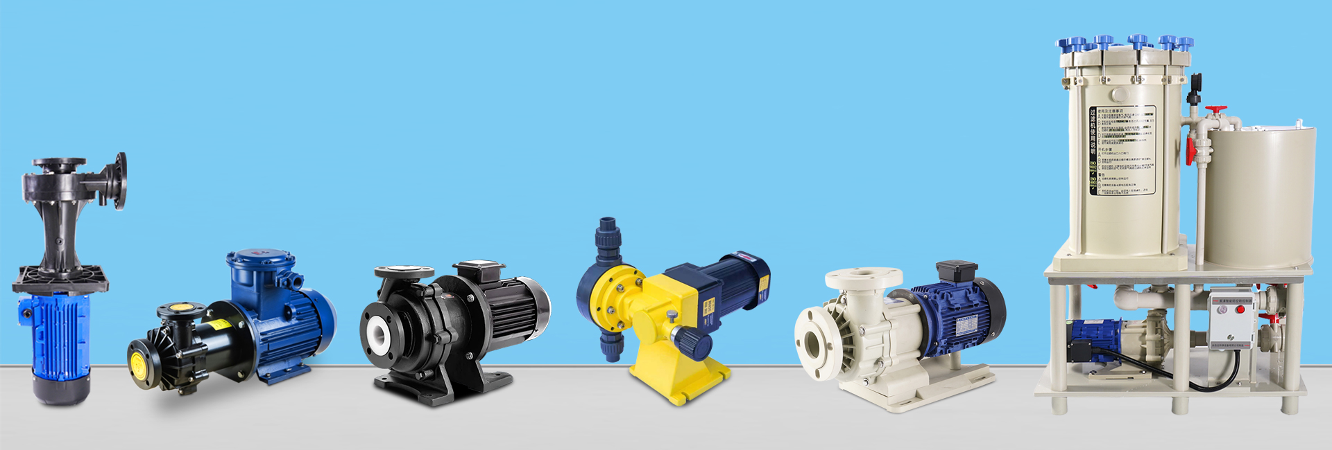
An industrial centrifugal pump is a dynamic fluid machine that transfers liquids by converting mechanical energy from a rotating impeller into kinetic and pressure energy. Known for its simple structure, stable flow, and easy operation, it is widely used in industries such as chemical, petroleum, power generation, metallurgy, and environmental protection.
This article provides a detailed overview of its principle, structure, types, applications, selection methods, and development trends.
1. Working Principle and Core Structure
The working principle of a centrifugal pump is based on centrifugal force.
When the motor drives the impeller to rotate at high speed, the liquid entering the impeller center gains kinetic energy and is thrown toward the periphery under centrifugal action. A low-pressure area forms at the impeller eye, continuously drawing in new liquid.
This process converts the motor’s mechanical energy into fluid pressure and kinetic energy, enabling continuous liquid delivery.
Key Components
Impeller – The core part determining pump performance.
Closed impeller: High efficiency, suitable for clean liquids.
Semi-open impeller: Handles fluids containing fine particles.
Open impeller: Anti-clogging, suitable for viscous or high-solid-content liquids.
Materials include cast iron, stainless steel, and corrosion-resistant plastics (e.g., UHMWPE, PVDF, PTFE).
Pump Casing – Usually spiral-shaped (volute). It collects the high-speed liquid and converts velocity energy into pressure energy.
In multi-stage pumps, diffusers or guide vanes are used to improve energy recovery.Sealing System – Prevents leakage or air ingress.
Common types include:Mechanical seal: Minimal leakage, ideal for precision applications.
Packing seal: Simple, suitable for fluids allowing slight leakage.
Magnetic seal: Zero leakage, perfect for toxic or corrosive fluids.
Balancing Device – Compensates for axial thrust produced by impeller rotation.
Typical designs: balance holes, double-suction impellers, balance discs.
2. Classification and Typical Applications
(1) Classification by Function
By Stage:
Single-stage pump – Low head, simple design.
Multi-stage pump – High head, used in boiler feed or high-pressure systems.
By Suction Type:
Single suction: Fluid enters from one side.
Double suction: Fluid enters both sides, providing high flow and balanced axial force.
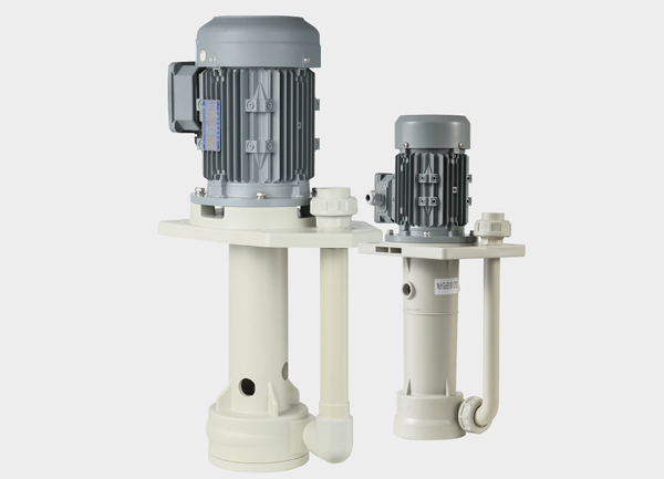
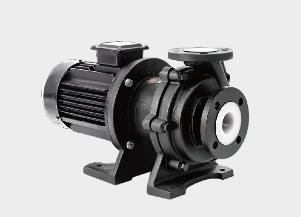
By Installation:
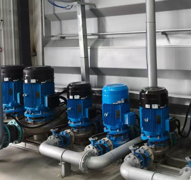
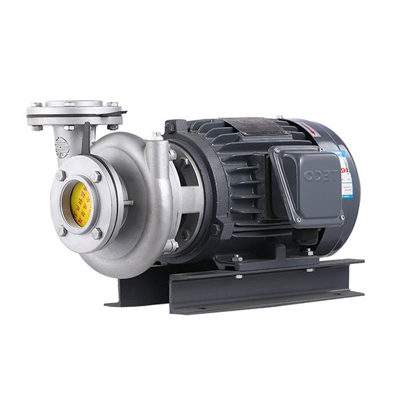
Horizontal pumps: Easy to maintain, require more floor space.
Vertical pumps: Space-saving, suitable for tanks or wells.
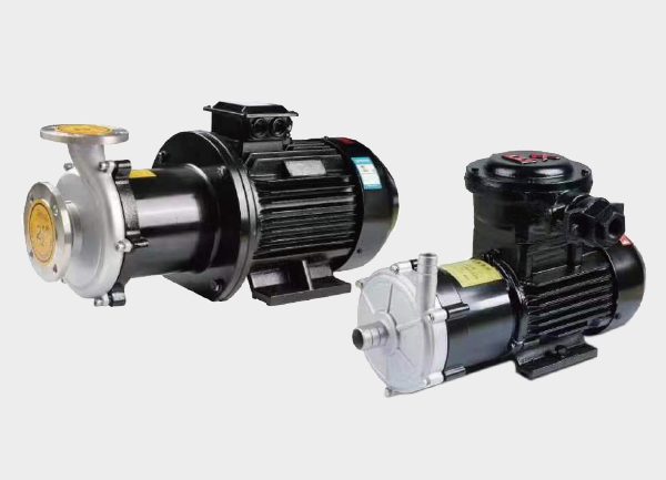
By Special Function:
Self-priming pump: No need for manual priming.
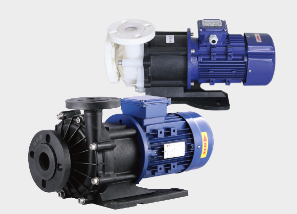
Magnetic drive pump: Seal-less and leak-free.
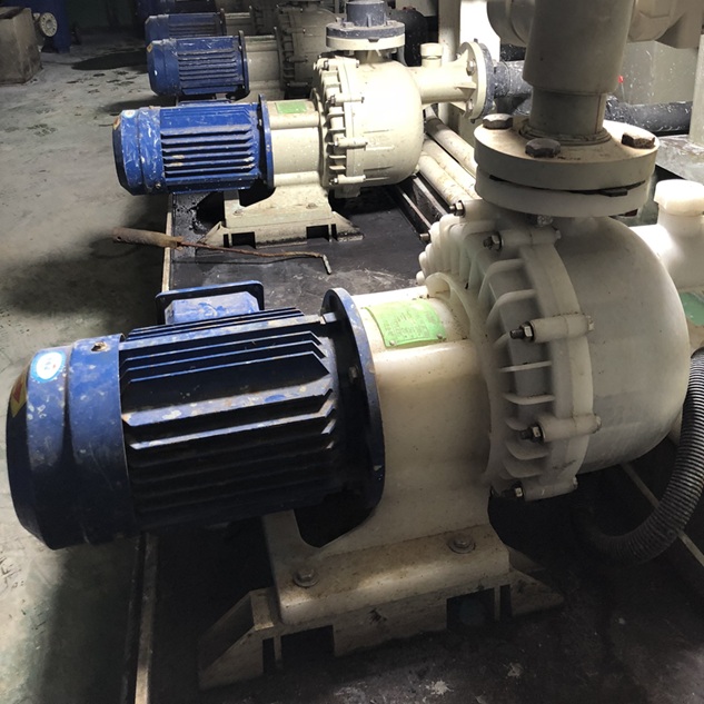
Corrosion-resistant pump: Made from engineering plastics or stainless steel for strong acid/alkali conditions.
(2) Industry Applications
Chemical & Petrochemical Industry
Handling acids, alkalis, oils, and chemical intermediates.
Example: FUH series plastic pumps are used for electrolyte and slurry transport in hydrometallurgy.Power & Energy Sector
Boiler feed (multi-stage pumps), circulating cooling (horizontal pumps), and coolant circulation in solar and lithium battery systems.Environmental Protection & Water Treatment
Wastewater lifting, desulfurization slurry, and sludge transfer.
These use wear-resistant open impellers to prevent clogging.Food & Pharmaceutical Industry
Sanitary centrifugal pumps made of stainless steel, designed for leak-free and easy-to-clean operation, ensuring product hygiene.
3. Selection Criteria and Calculation Methods
Selecting the right centrifugal pump depends on matching system parameters, fluid properties, efficiency, and reliability.
Core Parameter Calculations
Flow rate (Q):
Based on the maximum hourly flow, with a 5–15% safety margin (higher for solid-containing fluids).Head (H):
Htotal=Hstatic+Hloss+Hend+10%−15% marginH_{total} = H_{static} + H_{loss} + H_{end} + 10\%-15\% \text{ margin}
Example:
Lifting height 10 m + pipeline loss 5 m + terminal pressure 0.1 MPa (≈10 m) → total ≈ 28.5 m, so choose a ≥ 30 m head pump.NPSH (Net Positive Suction Head):
Ensure NPSHa > NPSHr to prevent cavitation and impeller damage.
Fluid Compatibility
Corrosion:
Mild: 304 stainless steel
Strong: 316L stainless steel or fluoroplastics (PTFE, PVDF)
Solid Content:
Fine particles: semi-open impeller
Large solids: open impeller + wear-resistant material (e.g., high-chromium cast iron)
Performance Curve Matching
The actual operating point (Q–H) should fall within the high-efficiency zone (80–100% of peak efficiency) to ensure stable operation and low energy consumption.
Structural & Auxiliary Considerations
Installation:
Horizontal pumps for ground setups; vertical pumps for confined spaces.Energy Efficiency:
Use VFD (Variable Frequency Drive) to reduce energy use by 20–50% when flow fluctuates.Special Conditions:
High-temperature fluids require cooling; solid-laden liquids need suction filters.
4. Installation and Maintenance
Installation Guidelines
Foundation must be solid; leveling tolerance ≤ 0.1/1000 (horizontal) and ≤ 0.05/1000 (vertical).
Pipe stress should not act on the pump; inlet/outlet must be well-supported.
Coupling alignment tolerance: radial ≤ 0.05 mm, axial ≤ 0.02 mm.
Routine Maintenance
Monitoring:
Regularly check flow, pressure, temperature, vibration, and motor current.Lubrication & Seals:
Replace oil periodically; inspect mechanical seals and adjust packing as needed.Anti-corrosion & Anti-wear:
Flush the pump after handling corrosive media and clean deposits from impeller or volute when handling slurries.
5. Development Trends and Emerging Technologies
Smart Monitoring and IoT Integration
Modern centrifugal pumps increasingly integrate sensors for real-time monitoring of vibration, temperature, and pressure.
With AI and big data analysis, systems can predict failures (e.g., impeller wear, bearing faults) before they occur.
Remote control and diagnostics platforms allow operators to adjust parameters and schedule maintenance from anywhere.
Energy Efficiency and Green Design
Use of permanent magnet synchronous motors and optimized impeller geometry improves efficiency by 5–10%, achieving IE4 or higher energy ratings.
Adoption of eco-friendly materials and closed-loop cooling systems helps reduce energy waste and environmental impact.
Adaptation to Extreme Conditions
Development of supercritical boiler feed pumps (operating > 25 MPa) and deep-sea mining pumps (high pressure, anti-blocking).
New energy applications such as hydrogen storage and high-purity fluid transfer in lithium battery production are driving customized centrifugal pump innovations.
Conclusion
The industrial centrifugal pump remains a cornerstone of fluid handling across industries.
Its ongoing evolution toward smart, efficient, and environmentally sustainable designs reflects the global trend toward digitalized and green manufacturing.
As IoT integration and advanced materials mature, centrifugal pumps will continue to play a vital role in modern process engineering and energy transition.