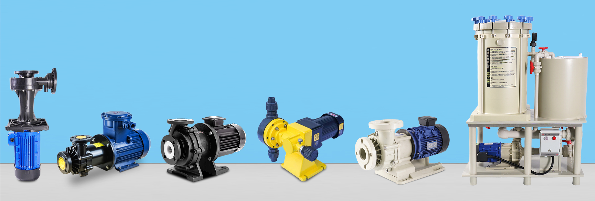
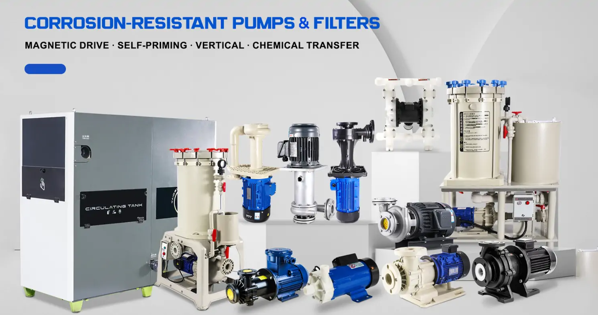


Self-priming pumps are widely used in industrial, municipal, and agricultural applications thanks to their ability to automatically evacuate air from the suction line and start pumping without manual priming. This guide provides a comprehensive overview of their core components, working principle, structural optimization, main classifications, selection parameters, and maintenance practices.
1. Key Components
A self-priming pump consists of several critical parts designed to achieve efficient gas-liquid mixing and reliable priming:
Pump Body: Built from high-strength cast iron or corrosion-resistant stainless steel, it supports internal components and forms flow channels for gas-liquid circulation.
Impeller: The power core, usually with 3–6 blades (fewer than conventional centrifugal pumps). Its forward-curved, semi-open design improves air suction and mixing performance.
Gas-Liquid Separation Chamber: Separates air (discharged via exhaust port) from degassed liquid (returned to impeller through the liquid return hole).
Liquid Return Hole: Ensures continuous liquid recirculation to maintain the priming process.
Sealing Device: Employs mechanical seals resistant to cavitation (e.g., SiC rotating ring, graphite stationary ring, fluororubber O-rings) to prevent leakage.
Motor: Converts electrical energy into mechanical power; power rating and protection class depend on working conditions.
2. Core Working Principle
Self-priming operation relies on gas-liquid circulation and separation, generally in three stages:
Initial Liquid Seal & Mixing
Before starting, priming liquid (50–70% of pump cavity volume) is filled.
The impeller (1450–2900 r/min) mixes liquid and suction air, forming a gas-liquid mixture with a 1:3–1:5 volume ratio.
Centrifugal Separation
The mixture enters the separation chamber, where air is discharged and liquid returns to the impeller.
The chamber liquid level stabilizes at 1/3–2/3 of chamber height.
Vacuum Suction
Continuous air removal creates a vacuum (0.02–0.05 MPa absolute pressure) in the suction line.
External liquid is drawn in, and full self-priming is achieved within 30–120 seconds.
3. Structural Optimization Focus
Pump Cavity Flow Channel:
Volute helix angle: 15°–25°
Separation chamber expansion angle: 8°–12°
Liquid return hole: 1/4–1/3 of impeller inlet diameter
Impeller Design:
Fewer blades (3–6) with forward-curved profile → enhanced air suction.
Semi-open structure → prevents air plugs, simplifies cleaning.
Cavitation Protection:
An inducer at the impeller inlet reduces vacuum, lowering NPSH requirement to 2–3 m for volatile fluids (e.g., gasoline).
4. Main Types of Self-Priming Pumps
Self-priming pumps can be classified by their gas-liquid mixing method:
Internal Mixing Type
Mixing at impeller inlet.
Self-priming height ≤ 8 m; efficiency 65–75%.
Longer priming time (60–120 s/10 m).
Best for clean, low-viscosity liquids.
External Mixing Type
Mixing at impeller outlet.
Self-priming height ≤ 9 m; efficiency 60–70%.
Faster priming (30–60 s/10 m).
Suitable for clean or slightly contaminated liquids.
Water Ring Wheel Type
Mixing occurs between water ring wheel and impeller.
Self-priming height ≤ 10 m; efficiency 70–80%.
Priming time 20–40 s/10 m.
Requires periodic water replenishment.
Jet Type (Ejector Type)
Mixing at ejector nozzle.
Self-priming height ≤ 12 m; efficiency 45–55%.
Fastest priming (15–30 s/10 m).
Suitable for high-viscosity or gas-containing liquids, but nozzle clogging risk exists.
5. Key Parameters & Selection Guidelines
Self-Priming Height (Hss)
Maximum vertical distance between pump shaft and liquid surface.
Corrected by:
Medium density: Hss′=Hss×1000/ρHss’ = Hss × 1000/ρ
Altitude: drop 0.8–1 m per 1000 m elevation
Temperature: At 80°C, Hss falls to 60–70% of value at 20°C
Gas-Liquid Ratio (α)
Industrial pumps: 1:1–1:3
Excess (>1:5) causes pump idling
Efficiency (η)
Transport stage: 60–80%
Mixing stage: 50–70% → avoid long-term operation in this stage
NPSH Requirement
Safe condition: NPSH≥NPSHr+0.5mNPSH ≥ NPSHr + 0.5 m
NPSHr is typically 10–20% lower than that of ordinary centrifugal pumps
Selection Logic
By Medium:
Particle-containing → semi-open impeller + wear-resistant materials
Corrosive → stainless steel or PVDF
High-viscosity → jet or external mixing type
By Working Conditions:
Reserve 10–20% margin for self-priming height (including pipe losses).
Choose pump based on maximum flow and head to maintain efficiency.
By Environment:
Diesel-driven → remote sites without electricity
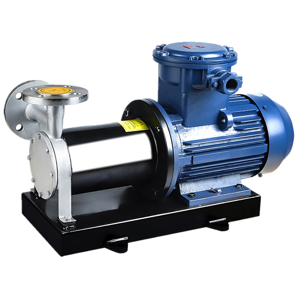
Explosion-proof motor → hazardous areas
Insulated pump body → low-temperature conditions (<0°C)
6. Maintenance Best Practices
To extend service life and ensure reliable operation:
Check separation chamber liquid level weekly; replenish if low.
Replace mechanical seals every 3000 hours; stop operation if leakage >5 drops/min.
Inspect impeller for cavitation pits (>1 mm) every 6 months; replace if damaged.
Clean liquid return hole and check pipelines if self-priming time increases by >20%.
Conclusion
Self-priming pumps combine automatic priming, strong adaptability, and efficient gas-liquid handling, making them indispensable in many industries. By understanding their design, types, key parameters, and maintenance requirements, engineers can select the right model and maximize reliability in real-world applications.