
1. Structural System: Detailed Breakdown by Functional Modules
1.1 Core Functional Modules
(1) Submerged Working Section
- Components: Impeller, pump body (casing), suction pipe, guide vane.
- Core Function: Complete liquid suction, pressurization, and transfer.
- Material Selection & Technical Requirements:
- Impeller: Selected based on medium characteristics:
① For clean media (e.g., electrolyte): Closed centrifugal impellers are used, typically made of Polyvinylidene Fluoride (PVDF) or 316L stainless steel to prevent impurity accumulation during transfer.
② For particle-containing media (e.g., sewage, mineral slurry): Open/semi-open impellers are preferred, with blade angles usually 15°–25° (to reduce clogging risks). Materials include wear-resistant alloys or silicon carbide-reinforced polypropylene (PP) for enhanced durability.
③ For high-viscosity media (e.g., resin): Twisted-blade impellers are adopted. Optimized blade curvature reduces fluid resistance, avoiding efficiency loss caused by high viscosity.
- Pump Body: Adapted to operating conditions:
① For strong corrosion scenarios (e.g., sulfuric acid, sodium hydroxide solutions): FRPP (fiberglass-reinforced PP) or PVDF is used. PVDF offers a maximum temperature resistance of 150°C, suitable for medium-to-high temperature corrosive media.
② For high-temperature conditions (e.g., high-temperature heat transfer oil, molten salt): Jacketed pump bodies are used, with 316L stainless steel as the main material. Cooling water or insulation media can be circulated in the jacket to stabilize the pump body temperature.
③ For food/pharmaceutical industries (e.g., dairy products, liquid medicine): 316L stainless steel is required, with an inner wall polishing precision of Ra ≤ 0.8μm to meet FDA hygiene certification and prevent medium contamination.
- Impeller: Selected based on medium characteristics:
(2) Transmission Section
- Components: Long/short shaft, bearing assembly, shaft sleeve.
- Core Function: Transmit motor power and ensure stable shaft rotation (reducing radial runout to avoid impeller-pump body friction).
- Material Selection & Technical Requirements:
- Shaft: Balances strength and corrosion resistance:
① For general conditions (e.g., room-temperature acid-base transfer): 316L stainless steel (tensile strength ≥ 520MPa) meets basic load requirements.
② For strong corrosion + high-load scenarios (e.g., seawater, concentrated hydrochloric acid transfer): Hastelloy C276 is used, offering excellent resistance to intergranular corrosion for long-term service in harsh media.
③ For ultra-long submersion depths (>3m): Segmented shafts connected by couplings are used to reduce shaft deflection (preventing bending and breakage during rotation). Deflection is controlled to ≤ 0.1mm/m.
- Bearings: Two types for dry/wet conditions:
① Dry bearings (motor end): Silicon nitride ceramic deep groove ball bearings, which operate without lubrication, resist wear, and adapt to high temperatures (max operating temperature ≤ 120°C).
② Submerged bearings (pump body end): Sliding bearings made of silicon carbide or PTFE (polytetrafluoroethylene), lubricated by the transferred liquid. The medium must be free of large particles to avoid bearing jamming.
- Shaft Sleeve: Protects the shaft from medium corrosion, with materials matching the shaft (e.g., 316L stainless steel sleeve for 316L shafts). Thickness is typically 3–5mm, and it can be replaced independently to reduce maintenance costs.
- Shaft: Balances strength and corrosion resistance:
(3) Drive Section
- Components: Motor, motor bracket, protective cover.
- Core Function: Provide power output and fix the pump structure (ensuring stability during operation).
- Material Selection & Technical Requirements:
- Motor: Adapted to environment and working conditions:
① For general environments (e.g., standard workshops): Y-series three-phase asynchronous motors (IP54 protection class for dust/water resistance, F-class insulation for max operating temperature 155°C).
② For explosive environments (e.g., chemical workshops, solvent transfer): Ex d IIB T4 Ga explosion-proof motors, complying with ATEX (EU) or GB3836 (China) standards to prevent sparks from triggering explosions.
③ For variable flow needs (e.g., dynamic flow adjustment): Variable-frequency motors, compatible with 0–50Hz speed regulation, and equipped with low-frequency heat dissipation (to avoid overheating at low speeds).
- Motor Bracket: Materials match the pump body (e.g., FRPP bracket for FRPP pumps, stainless steel bracket for stainless steel pumps). It must support the total weight of the motor and shaft, with deflection controlled to ≤ 0.1mm/m (preventing shaft misalignment due to bracket deformation).
- Motor: Adapted to environment and working conditions:
1.2 Key Auxiliary Systems
(1) Shaft Seal System (Core for Leak Prevention)
- Mechanical Seal: Suitable for low-viscosity, particle-free corrosive media (e.g., sulfuric acid, pharmaceutical intermediates), available in two types:
① Single-end mechanical seal: Simple structure and low cost, requiring the medium to have lubricity (e.g., ≥98% sulfuric acid). Seal faces use a “silicon carbide-silicon carbide” combination for corrosion resistance and long service life.
② Double-end mechanical seal: Equipped with an independent barrier fluid circulation system (e.g., ethylene glycol, white oil). Barrier fluid pressure is 0.1–0.2MPa higher than medium pressure, suitable for volatile, toxic media (e.g., chloroform, cyanides) to achieve “zero leakage.”
- Packing Seal: Suitable for particle-containing media allowing minimal leakage (e.g., municipal sewage, mineral slurry). Packing materials include “flexible graphite + PTFE” (max temperature 200°C) or “aramid fiber” (wear-resistant). Normal leakage is controlled at 10–20 drops/min (excessive leakage wastes media; insufficient causes packing burnout).
- Seal-Free Design: No mechanical contact, suitable for highly toxic, high-risk media (e.g., mercury, arsenides), available in two forms:
① Reverse impeller seal: Reverse blades on the impeller back generate negative pressure to offset medium pressure on the shaft seal, preventing leakage.
② Magnetic drive seal: The motor drives the impeller via a magnetic coupling (outer/inner magnets), with no mechanical shaft penetrating the pump body. It fully isolates the medium from the outside but is unsuitable for high-viscosity or ferromagnet-containing media (which interfere with magnetic transmission).
(2) Cooling/Insulation System (for Extreme Temperatures)
- Cooling System: When medium temperature >120°C (e.g., high-temperature resin, molten plastic), a “jacketed cooling chamber” is installed at the bearing housing or shaft seal. Cooling water (or oil) is circulated to control bearing temperature ≤85°C and seal face temperature ≤100°C (preventing bearing jamming and seal failure from overheating).
- Insulation System: When media are prone to crystallization (e.g., caustic soda solution, ammonium nitrate solution), a “jacketed insulation layer” is added to the pump body and suction pipe. Steam or hot water (5–10°C higher than the medium’s crystallization point) is circulated to prevent medium crystallization and flow channel blockage.
2. Working Principle: In-Depth Analysis from Fluid Mechanics
2.1 Start-Up Stage: Core Advantage of No Air Binding
2.2 Transfer Stage: Conversion of Centrifugal Force and Fluid Kinetic Energy
- As the impeller rotates at high speed, its blades exert “centrifugal thrust” on the liquid, pushing it from the impeller center (suction port) to the impeller edge (discharge port). During this process, the liquid’s “kinetic energy” and “pressure energy” increase significantly.
- The liquid enters the pump body’s “volute flow channel” (guide vane). The volute’s cross-sectional area expands from the inlet to the outlet, reducing liquid flow velocity and converting part of the “kinetic energy” into “pressure energy” to form a stable pressure difference.
- The pressure difference drives the liquid through the “discharge pipe” to the target location (e.g., reactor, storage tank). Meanwhile, the impeller center continuously maintains negative pressure, sucking liquid from the tank to achieve continuous transfer.
2.3 Key Issue: Prevention and Control of Cavitation
- Cavitation Hazards: When the pressure at the impeller center is lower than the medium’s saturated vapor pressure at the operating temperature, the liquid vaporizes to form bubbles. These bubbles collapse instantly when flowing to the high-pressure zone at the impeller edge, generating “water hammer” (local pressure up to 100MPa+). This causes honeycomb damage to the impeller, increased vibration, reduced flow/head, and even pump body damage in severe cases.
- Cavitation Prevention Design for Submerged Pumps:
- Shorten suction pipe length: The fully submerged pump body minimizes the suction pipe (typically <0.5m), reducing pressure loss during liquid suction (lower pressure loss means the impeller center pressure is less likely to drop below the saturated vapor pressure).
- Inducer at impeller inlet: For high-cavitation-risk conditions (e.g., high-temperature liquids, low-boiling-point media), a “helical inducer” is installed at the impeller inlet. The inducer pre-pressurizes the liquid to increase the impeller center pressure and prevent vaporization.
- Optimize impeller inlet parameters: Larger impeller inlet diameter and gentler inlet blade angles reduce liquid flow velocity at the impeller inlet (lower velocity = less pressure loss). Low-net positive suction head (NPSHr) impellers are used (smaller NPSHr = stronger cavitation resistance).
3. Classification: Scenario-Based Categorization by Core Characteristics
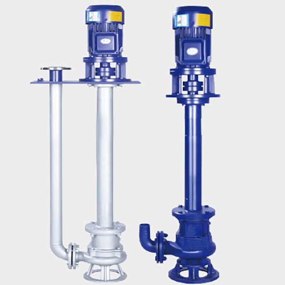
3.1 By Submersion Depth
- Short-Shaft Vertical Submerged Pumps: Submersion depth typically 0.5–1.5m. The shaft is short (no segmentation), with a simple structure and low cost. Suitable for low-tank-height scenarios (e.g., small reactor matching, laboratory small-flow transfer). Common models include the 50PVDF-15 (1m submersion depth, 15m³/h flow rate).
- Long-Shaft Vertical Submerged Pumps: Submersion depth 1.5–6m. The shaft is segmented (connected by couplings) and requires intermediate bearings (to reduce shaft deflection). Suitable for large tanks and deep-well liquid transfer (e.g., chemical tank farms, environmental sewage ponds). Some models support custom ultra-long shafts (submersion depth >6m), but shaft deflection must be controlled to avoid excessive vibration during rotation.
3.2 By Seal Type
- Mechanical Seal Type: Mainstream choice for particle-free, low-viscosity corrosive media (e.g., sulfuric acid, hydrochloric acid). Single/double-end seals are selected based on medium toxicity. Advantages: Low leakage (zero leakage for double-end seals). Disadvantages: Poor particle resistance (particles easily wear seal faces).
- Packing Seal Type: Suitable for particle-containing media allowing minimal leakage (e.g., sewage, mineral slurry). Advantages: Wear resistance and low maintenance costs (packing can be replaced independently). Disadvantages: Higher leakage (requires regular medium replenishment).
- Magnetic Seal Type: Seal-free design for highly toxic, high-risk media (e.g., mercury, cyanides). Advantages: Complete zero leakage. Disadvantages: Unsuitable for high-viscosity or ferromagnet-containing media (interferes with magnetic transmission efficiency).
3.3 By Drive Mode
- Standard Motor Drive Type: Suitable for stable flow/head conditions (e.g., fixed-process liquid circulation). Fixed motor speed (1450r/min or 2900r/min) with a simple structure and high cost-effectiveness.
- Variable-Frequency Motor Drive Type: Suitable for dynamic flow adjustment (e.g., reactor feeding, liquid level control). Speed is regulated via a frequency converter for 0–100% stepless flow adjustment. Significant energy savings (20–30% more efficient than standard motors).
4. Core Technical Parameters and Selection: Key Steps to Avoid Mismatch
4.1 Core Technical Parameters (Mandatory Confirmation)
- Flow Rate (Q): Unit: m³/h or L/s. Determined by process needs (e.g., 50m³/h feed rate for a reactor requires Q ≥ 50m³/h, with 10–20% margin). Conventional models range from 2.88–2000m³/h (small flows for laboratories, large flows for industrial tank farms).
- Head (H): Unit: m. The vertical height the pump can transfer liquid (must account for pipe resistance loss). Actual required head = vertical transfer height + pipe resistance loss (pipe resistance loss is typically 10–15% of the vertical height). Conventional models range from 12–50m (high-head models require multi-stage impellers).
- Submersion Depth (L): Unit: mm. The depth of the pump body submerged in liquid (must be ≤ tank height – 0.5m to avoid the pump top contacting the liquid surface). Conventional models range from 800–3000mm; ultra-long depths require customization (e.g., 6000mm).
- Medium Temperature (T): Unit: °C. Directly determines material selection (e.g., PVDF ≤150°C, FRPP ≤80°C). Conventional temperature range: -20–150°C (jacketed cooling for ultra-high temperatures, insulation for ultra-low temperatures).
- Medium Density (ρ): Unit: kg/m³. Affects motor power calculation (higher density = higher power demand). For example, water density = 1000kg/m³, 30% hydrochloric acid density = 1149kg/m³. Accurate values are required to avoid motor overload.
- Medium Viscosity (μ): Unit: mPa·s. For μ > 100mPa·s, high-viscosity dedicated impellers (e.g., twisted blades) are required to prevent flow/head loss. For example, resin with μ = 200mPa·s requires 30% more power than water.
- Particle Content and Size: For particle content >5% or particle size >0.15mm, open impellers + wear-resistant materials (e.g., silicon carbide-reinforced PP) are used to avoid flow channel clogging or component wear.
- Explosion-Proof Rating: Required for chemical and solvent transfer scenarios (e.g., Ex d IIB T4 Ga) to prevent motor sparks from causing safety accidents.
4.2 Selection Calculation (Key Formulas and Steps)
- Motor Power Calculation: Power (P, unit: kW) is critical for selection, calculated based on flow rate, head, medium density, and efficiency:
P = (Q × H × ρ × g) / (3600 × 1000 × η) × K
Where: Q = flow rate (m³/h), H = head (m), ρ = medium density (kg/m³), g = gravitational acceleration (9.81m/s²), η = pump efficiency (60–75% for conventional models), K = safety factor (1.2–1.3 to avoid overload).
Example: Transferring 30% hydrochloric acid (ρ = 1149kg/m³) with Q = 30m³/h, H = 18m, η = 70%:
P = (30×18×1149×9.81)/(3600×1000×0.7)×1.2 ≈ 2.97kW → Select a 3kW motor.
- Simplified Selection Flowchart:
- Confirm medium characteristics (chemical properties → temperature → particle content/size → viscosity → toxicity) → Initially determine wetted materials (e.g., PVDF for strong corrosion, wear-resistant PP for particles) and seal type (e.g., double-end mechanical seal for toxic media).
- Define process requirements (flow rate → head → variable-frequency need) → Screen models within parameter ranges (e.g., 80PVDF-30 for Q = 30m³/h, H = 18m).
- Calculate NPSHa (Net Positive Suction Head Available) and NPSHr (Net Positive Suction Head Required) → Ensure NPSHa > NPSHr + 0.5m (to prevent cavitation). NPSHa = tank liquid level height – pump suction port height – pipe resistance loss.
- Confirm installation conditions (tank height → submersion depth → explosion-proof rating) → Finalize the model (e.g., 80PVDF-30-Ex for 1.2m submersion depth and Ex d IIB T4 Ga rating).
5. Maintenance and Troubleshooting: Practical Guide to Extend Service Life
5.1 Daily Inspection (1–2 Times/Day, Key Parameter Monitoring)
- Bearing Temperature: Normal range: ≤85°C (rolling bearings), ≤95°C (sliding bearings). Measure with an infrared thermometer. If exceeding the limit: Check for insufficient lubrication (replenish grease for rolling bearings, verify medium lubrication for sliding bearings) or bearing wear (shut down for replacement).
- Shaft Seal Leakage: Normal leakage: ≤5 drops/min (mechanical seal), 10–20 drops/min (packing seal). If excessive: Inspect mechanical seal faces for wear (scratches, cracks) or tighten the packing gland moderately (1/4 turn each time to avoid burnout).
- Motor Current: Normal range: ≤90% of rated current. Monitor with an ammeter. If exceeding rated current: Check for impeller clogging (clean impurities), excessive medium viscosity/density (recalculate power), or motor winding short circuits (test insulation resistance with a megohmmeter).
- Vibration Level: Normal range: ≤5mm/s (RMS). Measure with a vibration tester. If excessive: Check for unbalanced impellers (impurity buildup), bent shafts (excessive radial runout), or bearing wear (troubleshoot sequentially).
- Discharge Pressure: Normal range: ±5% of the rated head pressure (e.g., ~0.18MPa for 18m head). If pressure drops sharply: Inspect for impeller damage (blade deformation), pipe leaks (check connection seals), or suction pipe clogging (clean filters).
5.2 Regular Overhaul (Scheduled Execution to Prevent Component Aging)
- Weekly Overhaul: Clean impurities from the impeller and suction pipe (flush with high-pressure water), check packing tightness (ensure the impeller rotates freely by hand) to prevent flow channel clogging and packing dry friction.
- Monthly Overhaul: Inspect bearing lubrication (replenish lithium-based grease for rolling bearings, filling 1/2–2/3 of the bearing internal space), measure shaft deflection with a dial indicator (control to ≤0.1mm/m) to avoid shaft bending and vibration.
- Quarterly/Semi-Annual Overhaul: Disassemble and inspect the seal assembly (check mechanical seal face flatness, replace aged packing), adjust the radial clearance between the impeller and pump body (control to 0.1–0.3mm; excessive clearance reduces head, insufficient causes friction).
- Annual Overhaul: Fully disassemble the pump, replace wearing parts (shaft sleeve, O-rings, packing, seals), and test motor insulation resistance with a megohmmeter (≥1MΩ at 25°C) to prevent short circuits.
5.3 Common Fault Troubleshooting (Logical Analysis)
(1) Insufficient Flow Rate
- Probable Causes (Ranked by Likelihood): ① Impeller clogging (impurity buildup on blades); ② Pipe connection leaks (excessive pressure loss); ③ Insufficient motor speed (low power voltage or frequency converter failure); ④ Impeller wear (blade deformation, reduced thickness).
- Solutions: ① Shut down and clean the impeller with high-pressure water; ② Inspect pipe connections and replace aged gaskets; ③ Stabilize power voltage (380V ±5%) and repair/replace the frequency converter; ④ Replace the impeller (match the original material).
(2) Abnormal Noise (Squealing or Low-Frequency Vibration)
- Probable Causes (Ranked by Likelihood): ① Cavitation (bubble formation at the impeller center); ② Bearing wear (damaged rolling bearing balls or excessive sliding bearing clearance); ③ Bent shaft (excessive radial runout); ④ Impeller-pump body friction (insufficient radial clearance).
- Solutions: ① Reduce pump installation depth (increase NPSHa) or replace with a low-NPSHr impeller; ② Replace bearings (match the working condition); ③ Straighten the shaft (replace if deflection >0.1mm); ④ Adjust the radial clearance to 0.1–0.3mm.
(3) Motor Overload and Tripping
- Probable Causes (Ranked by Likelihood): ① Excessive medium viscosity/density (e.g., designing for water but transferring high-viscosity resin); ② Impeller jamming (particles trapped between blades and pump body); ③ Motor winding short circuit (aged insulation); ④ Excessive head (actual required head exceeds the pump’s rated head).
- Solutions: ① Recalculate power and replace with a higher-power motor; ② Disassemble the pump to remove particles and install an ≥80-mesh filter at the suction pipe inlet; ③ Repair motor windings (or replace the motor); ④ Replace with a higher-head model (or reduce pipe resistance loss).
6. Typical Industry Application Cases (with Selection Insights)
Case 1: Chemical Industry – 30% Hydrochloric Acid Transfer (Strong Corrosion, Room Temperature)
- Operating Conditions: Q = 30m³/h, H = 18m, submersion depth = 1.2m, medium = 30% hydrochloric acid (ρ = 1149kg/m³, pH = 1, particle-free, 25°C), standard workshop (no explosion protection required).
- Selection Insights:
- Strong corrosion → Wetted materials: PVDF (resists hydrochloric acid, 150°C max temperature for room-temperature use).
- Particle-free, low viscosity → Closed centrifugal impeller (≈70% efficiency for high transfer efficiency).
- Non-toxic medium → Single-end mechanical seal (silicon carbide-silicon carbide faces, ≤5 drops/min leakage).
- Power calculation → 3kW standard motor.
- Final Model: Brand X 80PVDF-30 (Q = 30m³/h, H = 18m, 1.2m submersion depth, 3kW motor).
Case 2: Environmental Industry – Municipal Sewage Transfer (Particle-Containing, Room Temperature)
- Operating Conditions: Q = 50m³/h, H = 15m, submersion depth = 2.5m, medium = municipal sewage (sand particles, particle size ≤3mm, 5% content, ρ = 1050kg/m³, 20°C), outdoor sewage pond (no explosion protection required).
- Selection Insights:
- Particle-containing → Wetted materials: Wear-resistant PP (low cost, corrosion-resistant, wear-resistant), open impeller (wide flow channel to avoid clogging).
- Particle-induced seal wear → Packing seal (aramid fiber material, 10–20 drops/min leakage).
- 2.5m submersion depth → Long-shaft model with intermediate bearings (reduces shaft deflection).
- Power calculation → 4kW standard motor.
- Final Model: Brand Y 100GXL-50 (Q = 50m³/h, H = 15m, 2.5m submersion depth, 4kW motor).
Case 3: Pharmaceutical Industry – Liquid Medicine Circulation (High Purity, Low Temperature)
- Operating Conditions: Q = 10m³/h, H = 12m, submersion depth = 0.8m, medium = antibiotic liquid (particle-free, ρ = 1020kg/m³, 5°C, FDA-certified), clean workshop (no explosion protection required).
- Selection Insights:
- High purity → Wetted materials: 316L stainless steel (polished inner wall, Ra ≤ 0.8μm, FDA-compliant to avoid contamination).
- Particle-free, low viscosity → Closed impeller (polished to eliminate hygiene dead spots).
- Contamination prevention → Double-end mechanical seal (sterile water as barrier fluid to isolate the medium from the outside).
- Low temperature → No insulation (5°C is near room temperature, no crystallization risk).
- Final Model: Brand Z 65SS-10 (Q = 10m³/h, H = 12m, 0.8m submersion depth, 2.2kW motor).