
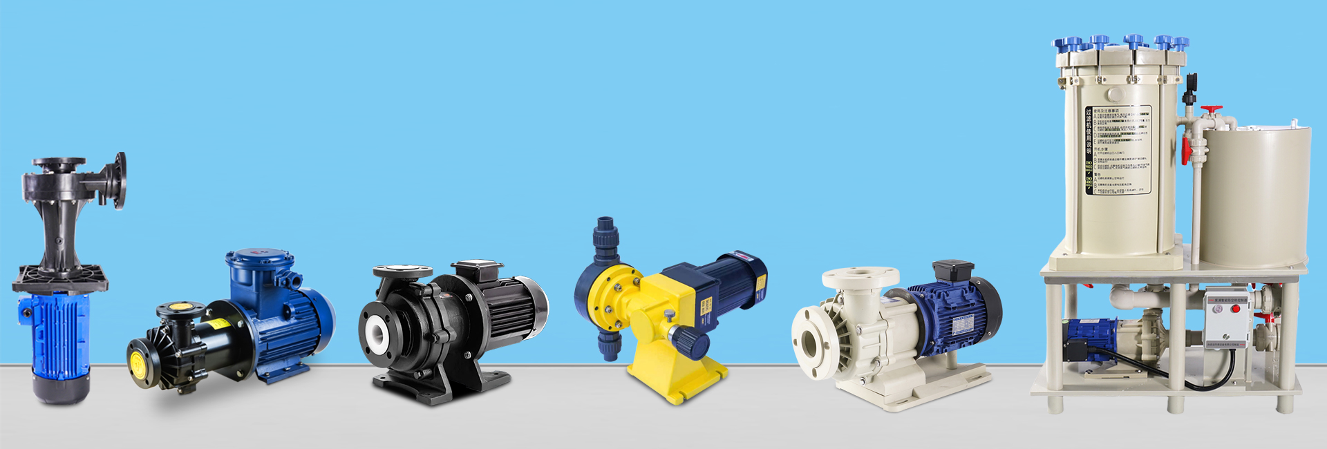
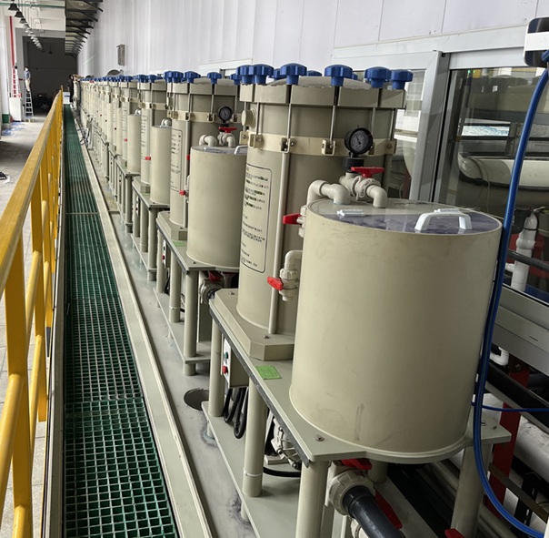
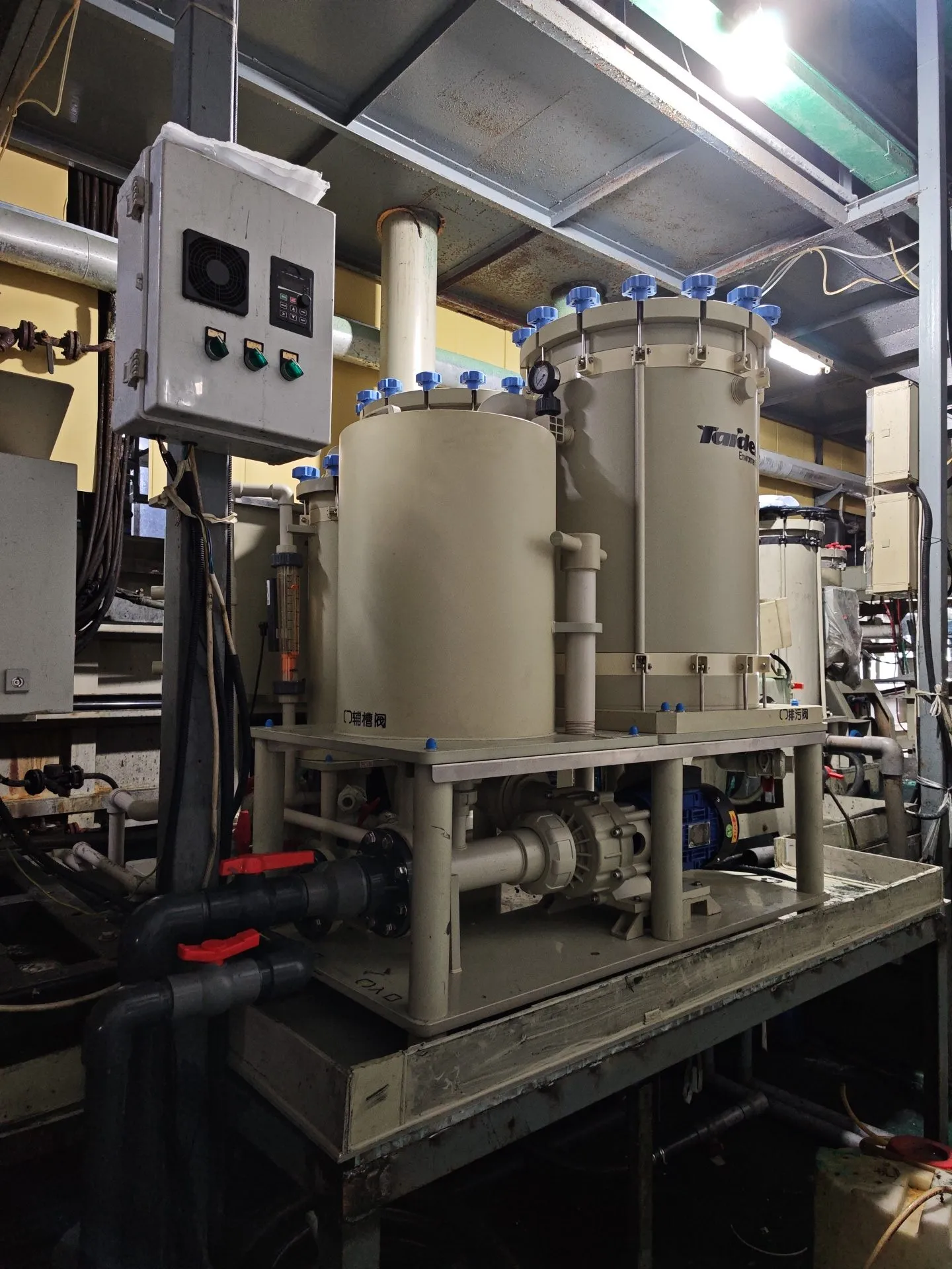
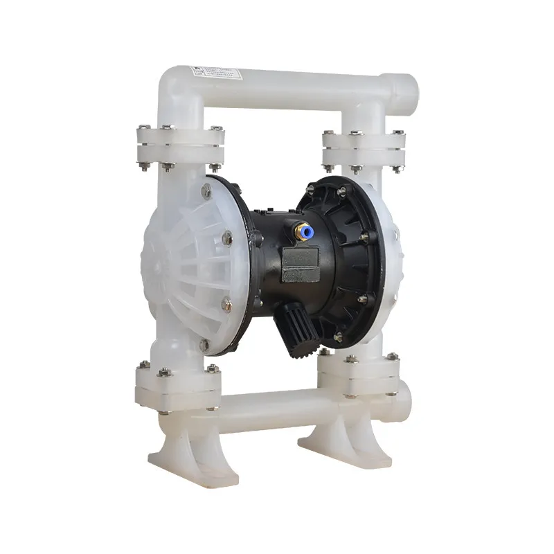

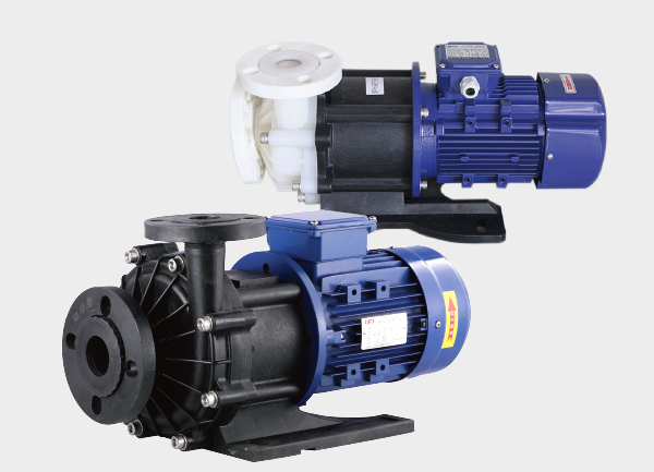
Magnetic drive pumps (also known as magnetically coupled pumps) achieve leak-free fluid transfer by transmitting torque through magnetic coupling instead of a direct mechanical connection. The system consists of two key components — an outer magnet and an inner magnet, separated by a containment shell (isolation sleeve). Understanding their structural differences is essential for proper pump selection, operation, and maintenance.
? 1. Basic Concept
A magnetic drive pump uses the outer magnetic rotor and inner magnetic rotor to form a magnetic coupling. The outer magnet receives the motor’s torque and transfers it to the inner magnet through a magnetic field.
The containment shell between them ensures complete fluid isolation, eliminating leakage risk.
? 2. Outer Magnet Structure
✅ Position and Function
-
Located outside the containment shell, directly connected to the motor shaft.
-
Responsible for receiving mechanical energy from the motor and transferring it magnetically to the inner rotor.
-
The outer magnet does not contact the pumped fluid.
✅ Structural Features
-
Mounted coaxially on the motor shaft.
-
Typically made of a steel shell with permanent magnets (such as NdFeB rare-earth magnets).
-
Magnetic poles are arranged in a circular pattern to create a strong magnetic field.
-
When the outer magnet rotates, it generates a rotating magnetic field that drives the inner magnet in synchronous motion.
✅ Key Characteristics
-
Directly coupled to the motor.
-
Isolated from the fluid.
-
Transfers mechanical torque efficiently.
? 3. Inner Magnet Structure
✅ Position and Function
-
Located inside the containment shell, fixed to the impeller.
-
Its main role is to receive the magnetic torque from the outer magnet and drive the impeller rotation.
-
The inner magnet is in direct contact with the pumped fluid.
✅ Structural Features
-
Integrated with the impeller assembly.
-
Protected by corrosion-resistant materials such as fluoroplastics, stainless steel, or titanium alloys.
-
Contains strong magnets aligned opposite to the outer magnet poles.
-
Rotates synchronously with the outer magnet to drive fluid flow.
✅ Key Characteristics
-
Contacts the pumped liquid directly.
-
Driven by magnetic force, not mechanically.
-
Endures hydraulic pressure and centrifugal force.
? 4. Comparison Between Inner and Outer Magnet Structures
| Item | Outer Magnet | Inner Magnet |
|---|---|---|
| Location | Outside the containment shell | Inside the containment shell |
| Drive Method | Directly driven by motor | Driven by magnetic force |
| Contact with Fluid | No | Yes |
| Function | Transmit torque | Receive torque and drive impeller |
| Material Requirements | High mechanical strength | High corrosion resistance |
| Common Issues | Demagnetization, misalignment | Overheating, demagnetization, cracking |
? 5. Working Principle (Simplified)
-
The motor drives the outer magnetic rotor.
-
The outer magnet generates a rotating magnetic field.
-
This magnetic field passes through the containment shell and drives the inner magnet synchronously.
-
The inner magnet rotates the impeller, pumping the liquid without any shaft seal or leakage.
✅ Conclusion
The outer magnet is located outside and transmits power, while the inner magnet is located inside and drives the impeller.
Together, they form a fully sealed, leak-free magnetic coupling system ideal for chemical, pharmaceutical, and industrial fluid transfer applications.